Change from zfs to mdadm and increase RAID5-Size

I’ve created via zfs a RAIDZ, which is roughly something like a RAID5 in the traditional way. It contained three disks and as time goes by, the resulting array (roughly double the size of a single disk) was nearly full.

I got an identical vendor and size disk like the first three disks and added it to the case. But the RAIDZ-expansion-feature is at the time of this writing still not completed and far from being included in Ubuntu releases.

So I came up with a plan to get a bigger array without loosing any data and without backing up all the data to an external system (I simply didn’t have *that* many spare disks).

mdadm has a „–grow“-feature, so I had to copy everything to a mdadm-Raid, but without any additional disks.

The plan looked like this:

Initial 3 disks in RAIDZ/zfs, set one as offline

Use the offline disk and the recently added new disk to a new mdadm (RAID-5), degraded from the start.

Copy everything from RAIDZ to mdadm.

Destroy the remaining zfspool and add the remaining two disks to mdadm, growing, reshaping and resyncing all in one big step.

The only possible setback would be a drive failure on ZFS after degrading the ZFS or a drive failure in the first two disks of the new mdadm. – This would always be a full disaster. So – fingers crossed – and everything worked fine. It took a few days (copy and resyncing is slow), but it finally worked.

To make sure that I don’t mess up, I created a demo-script to test the several steps and whether my idea worked at all.

It comes in two steps, the first one works until the start of resyncing the mdadm. The second one should be started AFTER the resyncing has finished. In the small demo files I used this happend very fast, in reality this could take days.

#!/bin/bash
mkdir -p /test
cd /test # Separates Verzeichnis
cd test/
rm -f 1.disk
rm -f 2.disk
rm -f 3.disk
rm -f 4.disk
losetup -D
umount /test/mnt
mdadm --stop /dev/md0
mdadm --remove /dev/md0
rm -f /test/backupfile.mdadm

echo "##### Creating images"
dd if=/dev/zero of=1.disk bs=1M count=256
dd if=/dev/zero of=2.disk bs=1M count=256
dd if=/dev/zero of=3.disk bs=1M count=256
dd if=/dev/zero of=4.disk bs=1M count=256
DISK1=$(losetup --find --show ./1.disk)
DISK2=$(losetup --find --show ./2.disk)
DISK3=$(losetup --find --show ./3.disk)
DISK4=$(losetup --find --show ./4.disk)
parted ./1.disk mklabel gpt
parted ./2.disk mklabel gpt
parted ./3.disk mklabel gpt
parted ./4.disk mklabel gpt
parted -a optimal -- ./1.disk mkpart primary 0% 100%
parted -a optimal -- ./2.disk mkpart primary 0% 100%
parted -a optimal -- ./3.disk mkpart primary 0% 100%
parted -a optimal -- ./4.disk mkpart primary 0% 100%

echo "##### Starting zfs pool on disk 1, 2, 3"
zpool create origtank raidz ${DISK1} ${DISK2} ${DISK3}

echo "##### zpool status"
zpool status -v origtank

echo "##### Creating test file on /origtank"
dd if=/dev/zero of=/origtank/data bs=1M count=300

echo "##### Setting third disk as faulty"
zpool offline origtank ${DISK3}

echo "##### zpool status"
zpool status -v origtank

echo "##### ls -lA /origtank; df -h /origtank"
ls -lA /origtank; df -h /origtank

echo "##### Creating new md0 from disk3 and disk4"
#parted -s ./3.disk mklabel gpt
#parted -s ./4.disk mklabel gpt
#parted -s -a optimal -- ./3.disk mkpart primary 0% 100%
#parted -s -a optimal -- ./4.disk mkpart primary 0% 100%
wipefs -a ${DISK3}
wipefs -a ${DISK4}
parted -s ${DISK3} set 1 raid on 
parted -s ${DISK4} set 1 raid on 
mdadm --create /dev/md0 -f --auto md --level=5 --raid-devices=3 ${DISK3} ${DISK4} missing

echo "##### mdstat"
cat /proc/mdstat
mdadm --detail /dev/md0

echo "## # ## Formatting /dev/md0"
sleep 2
mkfs.ext4 /dev/md0

echo "##### Mount md0"
mkdir /test/mnt
mount /dev/md0 /test/mnt

echo "##### ls -lA /test/mnt; df -h /test/mnt"
ls -lA /test/mnt; df -h /test/mnt

echo "## # ## Copy data"
sleep 2
# rsync --delete -avPH /origtank/ /test/mnt
rsync -avPH /origtank/ /test/mnt

echo "##### ls -lA /test/mnt; df -h /test/mnt"
ls -lA /test/mnt; df -h /test/mnt

echo "##### Creating NEW test file on /origtank"
dd if=/dev/zero of=/origtank/dataNEW bs=1M count=30

echo "## # ## Copy NEW data"
sleep 2
# rsync --delete -avPH /origtank/ /test/mnt
rsync -avPH /origtank/ /test/mnt

echo "##### ls -lA /test/mnt; df -h /test/mnt"
ls -lA /test/mnt; df -h /test/mnt

echo "## # ## destroying pool"
sleep 2
zpool destroy origtank

echo "## # ## Adding disks to md0"
sleep 2
mdadm --add /dev/md0 ${DISK1} ${DISK2}
mdadm --grow --raid-devices=4 /dev/md0 --backup-file=/test/backupfile.mdadm
cat /proc/mdstat

After the successful resync of the mdadm, you can resize the filesystem:

resize2fs /dev/md0
cat /proc/mdstat

This only takes a few minutes (even on very huge disks), but be patient! You can see the progress by looking at mdadm –detail.

echo "##### mdstat"
cat /proc/mdstat
mdadm --detail /dev/md0

echo "##### ls -lA /test/mnt; df -h /test/mnt"
ls -lA /test/mnt; df -h /test/mnt
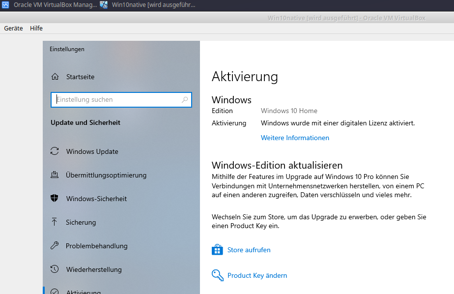
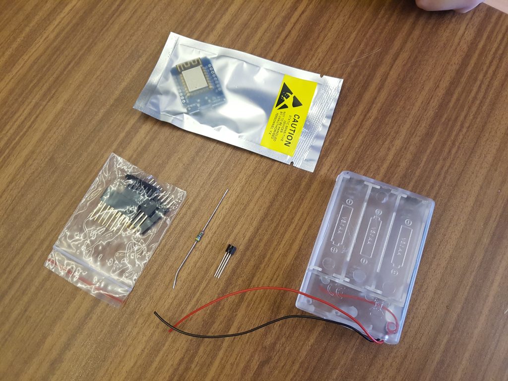
Image tricks with stable diffusion and clip-interrogator

When I got stable-diffusion to work, I really wanted to see what the AI would do on its own, letting it describe a given picture and re-create the picture from this description. How detailed can or should a description be?

First install the „clip-interrogator“:

python3 -m pip install --upgrade pip setuptools wheel
sudo apt install -y rustc cargo
pip install clip-interrogator

And here’s the sample python file. I got an error when I didn’t reassign/clear the „pipe“.

import torch
from torch import autocast
from diffusers import StableDiffusionPipeline
from PIL import Image
from clip_interrogator import Config, Interrogator

print("### Starting Stable Diffusion Pipeline")
pipe = StableDiffusionPipeline.from_pretrained("CompVis/stable-diffusion-v1-4")
pipe.to("cuda")

prompt = "a dark environment, two warriors standing on a chess field with swords drawn"
# prompt = "a laptop sitting on top of a wooden table"
steps = 50
width = 512
height = 512

print("### Creating images with Stable Diffusion")
with autocast("cuda"):
  for i in range(1):
    output = pipe(prompt, width=width, height=height, num_inference_steps=steps)
    image = output["images"][0]
    file = prompt.replace(" ", "_").replace(",", "")
    image.save(f"{file}-{i}.png")

pipe = "" # Destroy?
print("### Initializing Interrogator")
ci = Interrogator(Config(clip_model_name="ViT-L-14/openai"))
file = prompt.replace(" ", "_").replace(",", "")
for i in range(1):
  print("Loading file ", i)
  image = Image.open(f"{file}-{i}.png").convert('RGB')
  print(ci.interrogate(image))

Stable Diffusion on WSL on Windows

First install WSL2 as suggested by the many different websites out there. I installed it like this:

wsl --install -d Ubuntu-22.04

Open the installed Ubuntu and install the necessary packages for stable diffusion itself:

sudo apt update && sudo apt -y upgrade && sudo apt -y install git-lfs python3-pip
pip install torch --extra-index-url https://download.pytorch.org/whl/cu117
pip install diffusers transformers==4.26 scipy ftfy accelerate

Add CUDA-Support for the WSL (from this site):

wget https://developer.download.nvidia.com/compute/cuda/repos/ubuntu2204/x86_64/cuda-keyring_1.0-1_all.deb
sudo dpkg -i cuda-keyring_1.0-1_all.deb
sudo apt-get update
sudo apt-get -y install cuda

Write yourself a small python file (e.g. as main.py) which will enable the image generation and save the images to a file with the prompt name:

import torch
from torch import autocast
from diffusers import StableDiffusionPipeline

pipe = StableDiffusionPipeline.from_pretrained("CompVis/stable-diffusion-v1-4")
pipe.to("cuda")

prompt = "a dark environment, two warriors standing on a chess field with swords drawn"
steps = 50
width = 512
height = 512

with autocast("cuda"):
  for i in range(4):
    output = pipe(prompt, width=width, height=height, num_inference_steps=steps)
    image = output["images"][0]
    file = prompt.replace(" ", "_").replace(",", "")
    image.save(f"{file}-{i}.png")

Overleaf updaten

Eine alte Overleaf-Version lief bei mir lokal und diese wollte ich nun nach geraumer Zeit mal updaten. Installiert hatte ich die Version noch mithilfe des „docker-compose“, eine entsprechende Anleitung hatte ich hier bereits geschrieben.

Inzwischen hat sich overleaf etwas weiterentwickelt und man arbeitet mit dem Overleaf-Toolkit, welches inkompatibel zu meiner bisherigen Installation ist.

Zunächst musste ich von allem ein Backup erstellen, was aufgrund nicht-aktueller Beispiele von der Overleaf-Seite nicht trival war:

# Backup-Verzeichnis erstellen und hineinwechseln, hier als Beispiel:
mkdir -p ~/backupsharelatex/
cd ~/backupsharelatex/
# Die docker-compose.yml, welche zur Installation verwendet wurde, muss ebenfalls in dieses Verzeichnis. Danach kann das "exit 0" auskommentiert werden:
exit 0
# Backup mongodb
docker-compose exec mongo mongodump --archive="sharelatex-$(date +%Y%m%d).mongodb" --db="sharelatex"
docker cp mongo:sharelatex-$(date +%Y%m%d).mongodb .
tar cvfz ./sharelatex_data-$(date +%Y%m%d).tgz ~/sharelatex_data
docker-compose stop sharelatex

Dann führt man die Schritte aus dem Quick-Start-Guide aus. Hier muss man ggfs. noch die Einträge SHARELATEX_LISTEN_IP und SHARELATEX_PORT in der config/overleaf.rc ändern.

Am Ende (nachdem wir bin/up erfolgreich ausgeführt und wieder beendet haben) unsere alten MongoDB-Daten wieder zu importieren. Dazu brauchen wir im Backup-Verzeichnis wie bereits erwähnt die docker-compose.yml, sonst wird „mongo“ nicht gefunden.

docker cp ./sharelatex-$(date +%Y%m%d).mongodb mongo:sharelatex.mongodb
docker-compose exec mongo mongorestore --archive="sharelatex.mongodb"

Falls noch Daten im „data“-Verzeichnis eures alten sharelatex/data-Ordners liegen, müssen diese ebenfalls noch kopiert werden:

# "overleaf" ist hier das Verzeichnis welches man im "Quick-Start-Guide" angelegt hatte.
cd overleaf/data/sharelatex/data
sudo cp -r ~/sharelatex_data/data/* .

Jetzt ist alles wieder importiert und wir können das System über bin/start korrekt starten.

influxdb: backup and restore on Ubuntu 18.04

I ran into some trouble trying to backup and restore a InfluxDB to a new server. Here are the steps to correctly backup a database and restore it on the remote host.

On the source host, backup the InfluxDB you want while the influxdb is running:

# This will create a directory "backup" for DATABASE_NAME:
influxd backup -database DATABASE_NAME backup

Transfer the directory to the target machine and import the data (using default directories from influx):

sudo service influxdb stop # Restore works ONLY on stopped InfluxDB
sudo influxd restore -metadir /var/lib/influxdb/meta BACKUP_DIRECTORY
sudo influxd restore -database DATABASE_NAME -datadir /var/lib/influxdb/data BACKUP_DIRECTORY
sudo chown -R influxdb:influxdb /var/lib/influxdb
sudo service influxdb start

Overleaf installieren

Ich finde overleaf extrem cool, wollte aber für vergleichsweise sensible Daten nicht die öffentlich angebotene Instanz nutzen, sondern diese lieber lokal einsetzen. Da overleaf seinen Quellcode frei verfügbar gestellt hat, ist das ziemlich einfach umzusetzen.

Ich habe mir hierfür eine einfache „install.sh“ erstellt, welche die notwendigen Schritte ausführt. Die Datei sollte man als nicht-priviligierter Nutzer ausführen. Falls Docker (in einer Nicht-Community-Edition) bereits installiert ist, aber nicht läuft würde dieses Skript das Docker automatisch durch die Community Edition ersetzen, also bitte ggf. den Teil aus dem Skript herausnehmen.

#!/bin/bash
EMAILADRESS="" # Set this FIRST!
if [ -z ${EMAILADRESS} ]
then
  echo "Please set a value for EMAILADRESS first. That user will be made admin."
  exit 1
fi
. /etc/lsb-release
if (systemctl -q is-active docker)
then
  echo "Docker is already running, will NOT install."
else
  echo "### Initial apt update"
  sudo apt update
  echo "### Installing prerequisites"
  sudo apt -y install apt-transport-https ca-certificates curl software-properties-common
  echo "### Adding docker GPG key"
  curl -fsSL https://download.docker.com/linux/ubuntu/gpg | sudo apt-key add -
  echo "### Adding Repository"
  sudo add-apt-repository "deb [arch=amd64] https://download.docker.com/linux/ubuntu ${DISTRIB_CODENAME} stable"
  echo "### apt update for docker"
  sudo apt update
  echo "### Choosing docker-ce"
  sudo apt-cache policy docker-ce
  echo "### Installing docker-ce"
  sudo apt -y install docker-ce
  echo "### Checking im docker is running"
  if (systemctl -q is-active docker)
  then
    echo "### Docker is running"
  else
    echo "Docker is NOT running."
    exit 1
  fi
  echo "### Adding docker group"
  sudo groupadd docker
  newgrp docker
  sudo usermod -aG docker ${USER} ## Privilege user
fi
echo "### Installing docker-compose"
sudo apt -y install docker-compose
echo "### Pulling sharelatex-docker-image"
docker pull sharelatex/sharelatex
echo "### Pulling docker-compose.yml"
wget -nc https://raw.githubusercontent.com/overleaf/overleaf/master/docker-compose.yml
echo "### Modifying docker-compose.yml"
sed -i 's#- 80:80#- 2080:80#' docker-compose.yml # Only once, for the first "ports:"-directive
echo "### Running docker-compose"
docker-compose up -d sharelatex
docker exec sharelatex /bin/bash -c "cd /var/www/sharelatex; grunt user:create-admin --email=${EMAILADRESS}"
docker exec sharelatex wget http://mirror.ctan.org/systems/texlive/tlnet/install-tl-unx.tar.gz
docker exec sharelatex tar xvfz install-tl-unx.tar.gz
echo "#######################################################################"
echo "Execute 'cd install-tl-[0-9]*; ./install-tl'"
echo "Please choose 'y' to import settings, then choose 'I' for installation."
echo "Leave afterwards with 'exit'"
echo "#######################################################################"
docker exec -i -t sharelatex /bin/bash
docker exec sharelatex wget http://mirror.ctan.org/systems/texlive/tlnet/update-tlmgr-latest.sh -O /usr/local/texlive/2020/update-tlmgr-latest.sh
docker exec sharelatex chmod u+x /usr/local/texlive/2020/update-tlmgr-latest.sh
docker exec sharelatex /usr/local/texlive/2020/update-tlmgr-latest.sh -- --upgrade
docker exec sharelatex tlmgr update --self
docker exec sharelatex tlmgr install scheme-full
docker exec sharelatex luaotfload-tool -fu

Anschließend sollte auf dem aktuellen Host auf Port 2080 die Overleaf-Instanz erreichbar sein.

Die Installation von „scheme-full“ dauert eine ganze Weile, weil alles einzeln angestoßen wird. Bitte nicht ungeduldig werden, 1-2 Stunden je nach Rechnergeschwindigkeit sind hier völlig normal.

Falls merkwürdige Fehler auftauchen (z.B. dass die Silbentrennung von ngerman bzw. german nicht geladen werden kann), dann kann das an einer veralteten TeXLive-Installation im Docker-Container liegen. Bei mir war im vorgefertigen Docker noch TeXLive 2019 installiert, welches man manuell auf 2020 updaten kann (seit dem 07.04. muss dies ausgeführt werden, daher habe ich es in das Skript oben integriert, leider muss man durch das interaktiv „install-tl“-Skript die Fragen selbst beantworten):

docker exec -i -t sharelatex /bin/bash
wget http://mirror.ctan.org/systems/texlive/tlnet/install-tl-unx.tar.gz
tar xvfz install-tl-unx.tar.gz
cd install-tl-*
./install-tl

Die Fragen der Installation sollte man einfach so übernehmen, das „neue“ TeXLive wird dann in die Verzeichnisse des 2019er-TeXLive installiert. Im Idealfall kann man also direkt nach dem Starten von install-tlmit einem I die Installation ausführen. Das Upgrade dauert auch wieder lange, da wieder ca. 4000 Pakete installiert werden.

Convert Samsung Notes sdoc-files to txt

During a holiday I typed quite a few information in the „SNotes“-App on my Samsung Galaxy S8 phone. After my return, I couldn’t just easily copy the written text on my PC, I had to „export“ to sdoc and save them.

The trouble is, that sdoc-Files can’t be opened easily on a PC. So I figured it out on my own how to get the most of the information out of the file.

First of all you should know that every .sdoc-file is really only a .zip, so you can easily append .zip oder change the .sdoc to .zip and extract the file. That way you have access to all data (like pictures or audio). The written text is included in the „text.dat“. Unfortunately, there are quite a few bytes inside the files that are unnecessary. Here’s my command I’m using to convert the included text to plain readable text. This even works with german umlauts:

xxd -p text.dat | sed 's/00//g; s/^1d12//;' | tr -d '\n' | sed 's/01010301/0a/' | xxd -r -p | sed 's/EOF$//' >text.txt

It removes all Zero-Bytes, the Header (1d12) and the seperator between the title and the body (01010301). The final „EOF“ is unnecessary as well and afterwards everything is written to text.txt, works like a charm.

Ambilight

Hier meine angepasste Version, die mit Ambibox (unter Windows) kommuniziert und ein Ambilight vergleichsweise einfach ermöglicht. Die LED-Anzahl und ggf. ein paar weitere Parameter müssen natürlich noch angepasst werden.

#include "FastLED.h"
#include "Arduino.h"

#define ANALOG_MODE_AVERAGE  0
#define ANALOG_MODE_LAST_LED 1
#define FASTLED_ESP8266_D1_PIN_ORDER

/**************************************
   S E T U P
   set following values to your needs
 **************************************/

#define INITIAL_LED_TEST_ENABLED true
#define INITIAL_LED_TEST_BRIGHTNESS 32  // 0..255
#define INITIAL_LED_TEST_TIME_MS 2000  // 10..

// Number of leds in your strip. set to "1" and ANALOG_OUTPUT_ENABLED to "true" to activate analog only
// As of 26/1/2017:
// 582 leaves ZERO bytes free and this
// 410 is ok
// tested with 500 leds and is fine (despite the warning)
#define MAX_LEDS 7+7+11+1

// type of your led controller, possible values, see below
//#define LED_TYPE APA102
#define LED_TYPE WS2812

// 3 wire (pwm): NEOPIXEL BTM1829 TM1812 TM1809 TM1804 TM1803 UCS1903 UCS1903B UCS1904 UCS2903 WS2812 WS2852
//               S2812B SK6812 SK6822 APA106 PL9823 WS2811 WS2813 APA104 WS2811_40 GW6205 GW6205_40 LPD1886 LPD1886_8BIT 
// 4 wire (spi): LPD8806 WS2801 WS2803 SM16716 P9813 APA102 SK9822 DOTSTAR

// For 3 wire led stripes line Neopixel/Ws2812, which have a data line, ground, and power, you just need to define DATA_PIN.
// For led chipsets that are SPI based (four wires - data, clock, ground, and power), both defines DATA_PIN and CLOCK_PIN are needed

// DATA_PIN, or DATA_PIN, CLOCK_PIN
#define LED_PINS D2        // 3 wire leds
// #define LED_PINS D3, D2  // 4 wire leds

// #define COLOR_ORDER RBG  // colororder of the stripe, set RGB in hyperion
// #define COLOR_ORDER BGR  // colororder of the stripe, set RGB in hyperion
#define COLOR_ORDER GRB  // colororder of the stripe, set RGB in hyperion

#define OFF_TIMEOUT 0    // ms to switch off after no data was received, set 0 to deactivate

// analog rgb uni color led stripe - using of hyperion smoothing is recommended
// ATTENTION  this pin config is default for atmega328 based arduinos, others might work to
//            if you have flickering analog leds this might be caused by unsynced pwm signals
//            try other pins is more or less the only thing that helps
#define ANALOG_OUTPUT_ENABLED false
#define ANALOG_MODE           ANALOG_MODE_LAST_LED  // use ANALOG_MODE_AVERAGE or ANALOG_MODE_LAST_LED
#define ANALOG_GROUND_PIN     8                     // additional ground pin to make wiring a bit easier
#define ANALOG_RED_PIN        9
#define ANALOG_GREEN_PIN      10
#define ANALOG_BLUE_PIN       11

// overall color adjustments
#define ANALOG_BRIGHTNESS_RED   255              // maximum brightness for analog 0-255
#define ANALOG_BRIGHTNESS_GREEN 255              // maximum brightness for analog 0-255
#define ANALOG_BRIGHTNESS_BLUE  255              // maximum brightness for analog 0-255

#define BRIGHTNESS 255                      // maximum brightness 0-255
#define DITHER_MODE BINARY_DITHER           // BINARY_DITHER or DISABLE_DITHER
#define COLOR_TEMPERATURE CRGB(255,255,255) // RGB value describing the color temperature
#define COLOR_CORRECTION  TypicalLEDStrip   // predefined fastled color correction
//#define COLOR_CORRECTION  CRGB(255,255,255) // or RGB value describing the color correction

// Baudrate, higher rate allows faster refresh rate and more LEDs
//#define serialRate 460800      // use 115200 for ftdi based boards
#define serialRate 115200     // use 115200 for ftdi based boards
//#define serialRate 500000         // use 115200 for ftdi based boards


/**************************************
   A D A L I G H T   C O D E
   no user changes needed
 **************************************/

// Adalight sends a "Magic Word" (defined in /etc/boblight.conf) before sending the pixel data
uint8_t prefix[] = {'A', 'd', 'a'}, hi, lo, chk, i;

unsigned long endTime;

// Define the array of leds
CRGB leds[MAX_LEDS];

// set rgb to analog led stripe
void showAnalogRGB(const CRGB& led) {
  if (ANALOG_OUTPUT_ENABLED) {
    byte r = map(led.r, 0,255,0,ANALOG_BRIGHTNESS_RED);
    byte g = map(led.g, 0,255,0,ANALOG_BRIGHTNESS_GREEN);
    byte b = map(led.b, 0,255,0,ANALOG_BRIGHTNESS_BLUE);
    analogWrite(ANALOG_RED_PIN  , r);
    analogWrite(ANALOG_GREEN_PIN, g);
    analogWrite(ANALOG_BLUE_PIN , b);
  }
}

// set color to all leds
void showColor(const CRGB& led) {
  #if MAX_LEDS > 1 || ANALOG_OUTPUT_ENABLED == false
  LEDS.showColor(led);
  #endif
  showAnalogRGB(led);
}

// switch of digital and analog leds
void switchOff() {
  #if MAX_LEDS > 1 || ANALOG_OUTPUT_ENABLED == false
  memset(leds, 0, MAX_LEDS * sizeof(struct CRGB));
  FastLED.show();
  #endif
  showAnalogRGB(leds[0]);
}

// function to check if serial data is available
// if timeout occured leds switch of, if configured
bool checkIncommingData() {
  boolean dataAvailable = true;
  while (!Serial.available()) {
    if ( OFF_TIMEOUT > 0 && endTime < millis()) {
      switchOff();
      dataAvailable = false;
      endTime = millis() + OFF_TIMEOUT;
    }
  }

  return dataAvailable;
}

// main function that setups and runs the code
void setup() {
  Serial.begin(serialRate);

  // analog output
  if (ANALOG_OUTPUT_ENABLED) {
    // additional ground pin to make wiring a bit easier
    pinMode(ANALOG_GROUND_PIN, OUTPUT);
    digitalWrite(ANALOG_GROUND_PIN, LOW);
    pinMode(ANALOG_BLUE_PIN , OUTPUT);
    pinMode(ANALOG_RED_PIN  , OUTPUT);
    pinMode(ANALOG_GREEN_PIN, OUTPUT);
  }

  int ledCount = MAX_LEDS;
  if (ANALOG_MODE == ANALOG_MODE_LAST_LED) {
    ledCount--;
  }

  #if MAX_LEDS > 1 || ANALOG_OUTPUT_ENABLED == false
    FastLED.addLeds<LED_TYPE, LED_PINS, COLOR_ORDER>(leds, ledCount);
  #endif
  
  // color adjustments
  FastLED.setBrightness ( BRIGHTNESS );
  FastLED.setTemperature( COLOR_TEMPERATURE );
  FastLED.setCorrection ( COLOR_CORRECTION );
  FastLED.setDither     ( DITHER_MODE );

  // initial RGB flash
  #if INITIAL_LED_TEST_ENABLED == true
  for (int v=0;v<INITIAL_LED_TEST_BRIGHTNESS;v++)
  {
    showColor(CRGB(v,v,v));  
    delay(INITIAL_LED_TEST_TIME_MS/2/INITIAL_LED_TEST_BRIGHTNESS);
  }
 
  for (int v=0;v<INITIAL_LED_TEST_BRIGHTNESS;v++)
  {
    showColor(CRGB(v,v,v));  
    delay(INITIAL_LED_TEST_TIME_MS/2/INITIAL_LED_TEST_BRIGHTNESS);
  }
  #endif
  showColor(CRGB(0, 0, 0));

  Serial.print("Ada\n"); // Send "Magic Word" string to host


  boolean transmissionSuccess;
  unsigned long sum_r, sum_g, sum_b;

  // loop() is avoided as even that small bit of function overhead
  // has a measurable impact on this code's overall throughput.
  for(;;) {
    // wait for first byte of Magic Word
    for (i = 0; i < sizeof prefix; ++i) {
      // If next byte is not in Magic Word, the start over
      if (!checkIncommingData() || prefix[i] != Serial.read()) {
        i = 0;
      }
    }

    // Hi, Lo, Checksum
    if (!checkIncommingData()) continue;
    hi = Serial.read();
    if (!checkIncommingData()) continue;
    lo = Serial.read();
    if (!checkIncommingData()) continue;
    chk = Serial.read();

    // if checksum does not match go back to wait
    if (chk != (hi ^ lo ^ 0x55)) continue;

    memset(leds, 0, MAX_LEDS * sizeof(struct CRGB));
    transmissionSuccess = true;
    sum_r = 0;
    sum_g = 0;
    sum_b = 0;

    int num_leds = min ( MAX_LEDS, (hi<<8) + lo + 1 );

    // read the transmission data and set LED values
    for (int idx = 0; idx < num_leds; idx++) {
      byte r, g, b;
      if (!checkIncommingData()) {
        transmissionSuccess = false;
        break;
      }
      r = Serial.read();
      if (!checkIncommingData()) {
        transmissionSuccess = false;
        break;
      }
      g = Serial.read();
      if (!checkIncommingData()) {
        transmissionSuccess = false;
        break;
      }
      b = Serial.read();
      leds[idx].r = r;
      leds[idx].g = g;
      leds[idx].b = b;
      #if ANALOG_OUTPUT_ENABLED == true && ANALOG_MODE == ANALOG_MODE_AVERAGE
          sum_r += r;
          sum_g += g;
          sum_b += b;
      #endif
    }

    // shows new values
    if (transmissionSuccess) {
      endTime = millis() + OFF_TIMEOUT;
      #if MAX_LEDS > 1 || ANALOG_OUTPUT_ENABLED == false
      FastLED.show();
      #endif

      #if ANALOG_OUTPUT_ENABLED == true
        #if ANALOG_MODE == ANALOG_MODE_LAST_LED
          showAnalogRGB(leds[MAX_LEDS-1]);
        #else
          showAnalogRGB(CRGB(sum_r/MAX_LEDS, sum_g/MAX_LEDS, sum_b/MAX_LEDS));
         #endif
      #endif
    }
  }
} // end of setup

void loop() {
  // Not used. See note in setup() function.
}

Use native Windows 10 via VirtualBox in Linux

I have a dual-boot setup on my computer, the Windows 10 was already installed and is locked to the hardware („digital license“). After resizing the Windows partition, I was able to install ubuntu as a secondary operation system. I could change between system after a reboot, but I was unsatisfied that I had to reboot from Linux to Windows only for a short usage of the latter.

So I installed VirtualBox and instead of creating a new virtual Windows 10 which would require a different license, I figured out how to use the raw partition with the activated windows 10 within VirtualBox.

VirtualBox does support access to the raw disk, but there are some ceavats that need to be considered.

First, you’ll have to figure out which partition are EFI and belong the Windows 10 as well. Using gparted, you’ll quickly find the partitons which are labeled like this:

EFI system partition (fat32)
Microsoft reserved partition (unknown)
Basic data partiton (ntfs)

Using these partition information, you can now create a „raw vmdk“ file which can be used by VirtualBox. If the mentioned partitions are for example /dev/sda1, /dev/sda2 and /dev/sda3, issue this command (compensate for different device names, if necessary):

sudo VBoxManage internalcommands createrawvmdk -filename win10native.vmdk -rawdisk /dev/sda -partitions 1,2,3 -relative

I have named the raw file here „win10native.vmdk“, it will create a secondary file with „-pt.vdmk“ at the end, we won’t be using it here, but please leave it where it is. Now change the ownership of these two files to the user you want to use VirtualBox with (change „user“ and „group“ accordingly):

sudo chown -R user:group win10native*

Your current user must have disk access to continue. Beware, this literally means that this user is essentially given root rights as he can access all data on any disc. (Change „user“ accordingly)

sudo usermod -aG disk,vboxusers user

Enable „EFI“-Support in your System Settings of your VirtualBox.

If you would boot now your new virtual machine with the win10native.vmdk attached, Windows 10 can be booted, but as it detects different hardware, it will complain that it is not activated. To circumvent this, we have to read your system-uuid and write it to the virtual machine. The following command will print you the ID:

sudo dmidecode -s system-uuid

Modify your VM to change the system-uuid to the value you have just received (correct the XXX accordingly):

VBoxManage modifyvm Win10native --hardwareuuid XXXXXXXX-XXXX-XXXX-XXXX-XXXXXXXXXXXX

If you boot now, you’ll most certainly only see a shell from „GRUB 2.02“ or something similar, as grub can’t find the Windows bootloader, this information is missing inside the UEFI from VirtualBox (and grub can’t find its root partition). To test your windows installation and activation, simply type these commands (you might have to change the „(hd0,gpt1)“-part – in fact, as the „root“ variable was already pointing to the correct device, I didn’t need to change it at all) and you can boot into windows. Remember that you only have the US-keyboard-layout.

insmod chain
set root=(hd0,gpt1)
chainloader /EFI/Microsoft/Boot/bootmgfw.efi
boot

And here’s the result with an activated Windows 10 within Virtual Box. I can still boot native into Windows 10 without any further trouble. Don’t forget to install the VirtualBox Guest Addins for more comfort.

To circumvent the grub shell, you’ll have to enter the UEFI of VirtualBox. Boot the VM and immediatly (!) hit the F12-Button to enter the settings.

Add Boot Option and select the entry beginning with „SYSTEM“, this will let you traverse the directory path. Navigate to EFI/Microsoft/Boot/bootmgfw.efi and press ENTER. Add something at „Input the description“, press „F10“ and acknowledge with „Y“ then commit your changes.

In Boot -> Change Boot Order, select the EFI-Entry together with your newly created entry, highlight your entry and press „+“ until it is on the very top.

As the last step, „Reset system“ and it will boot Windows 10 directly. The changes made here a NOT permanent and will be lost the next time you boot (hey, at least you don’t have to type all those command on a us-layout-keyboard). This is a known issue by VirtualBox.


Dualboot cryptsetup ubuntu reparieren

Natürlich können die Bootpartitionen und die verschlüsselte Partition völlig andere Namen haben.

cryptsetup luksOpen /dev/nvme0n1p6 nvme0n1p6_crypt
mount /dev/mapper/nvme0n1p6_crypt /mnt
# boot und boot/efi können nun unter /mnt/etc/fstab ausgelesen werden
mount /dev/nvme0n1p5 /mnt/boot
mount /dev/nvme0n1p1 /mnt/boot/efi
cp /proc/mounts /mnt/etc/mtab
mount -o bind /dev /mnt/dev
mount -o bind /sys /mnt/sys
mount -t proc /proc /mnt/proc
chroot /mnt /bin/bash
update-initramfs -k all -c
grub-install
update-grub

Nach und nach dies hier ausführen. Die Befehle am Ende, die mit einem # gekennzeichnet sind, müssen innerhalb der chroot-Umgebung ausgeführt werden.

/dev/nvme1n1p6 ist das mit cryptsetup bereits verschlüsselte root-Dateisystem und muss ggfs. hier angepasst werden. Dasselbe gilt für die Boot- und EFI-Partitionen.

#!/bin/bash
cryptsetup luksOpen /dev/nvme1n1p6 nvme1n1p6_crypt
mount /dev/mapper/nvme1n1p6_crypt /mnt

mount /dev/nvme1n1p5 /mnt/boot
mount /dev/nvme0n1p1 /mnt/boot/efi
cp /proc/mounts /mnt/etc/mtab
mount -o bind /dev /mnt/dev
mount -o bind /sys /mnt/sys
mount -t proc /proc /mnt/proc
chroot /mnt /bin/bash
# update-initramfs -k all -c
# mount -t efivarfs none /sys/firmware/efi/efivars
# grub-install --target=x86_64-efi --efi-directory=/boot/efi/ --bootloader-id=grub
# update-grub

Create additional tool (arp-scan) for LibreELEC

I wanted my Rasperry Pi 2, which was running LibreELEC, to additionally scan for specific network devices. I didn’t want to change the LibreELEC, as I was very satisfied with it. So here’s how I managed to cross-compile on my linux box the tool `arp-scan`.

1.) Get the LibreELEC.tv-Source and compile an image.

Make sure that this works before continuing with anything else. I managed to compile the 9.0-devel version.

Instructions are given on the LibreELEC-Wiki

2.) Create the arp-scan directory and the package.mk

mkdir -p packages/tools/arp-scan
cat >packages/tools/arp-scan/package.mk <<EOF
################################################################################
#      This file is part of LibreELEC - https://libreelec.tv
#      Copyright (C) 2018-present Team LibreELEC
#
#  LibreELEC is free software: you can redistribute it and/or modify
#  it under the terms of the GNU General Public License as published by
#  the Free Software Foundation, either version 2 of the License, or
#  (at your option) any later version.
#
#  LibreELEC is distributed in the hope that it will be useful,
#  but WITHOUT ANY WARRANTY; without even the implied warranty of
#  MERCHANTABILITY or FITNESS FOR A PARTICULAR PURPOSE.  See the
#  GNU General Public License for more details.
#
#  You should have received a copy of the GNU General Public License
#  along with LibreELEC.  If not, see <http://www.gnu.org/licenses/>.
################################################################################
 
PKG_NAME="arp-scan"
PKG_VERSION="1.9"
PKG_ARCH="arm"
PKG_LICENSE="GPL"
PKG_SITE="http://www.nta-monitor.com/wiki/index.php/Arp-scan_Installation_Guide"
PKG_URL="https://github.com/royhills/arp-scan/releases/download/$PKG_VERSION/arp-scan-$PKG_VERSION.tar.gz"
PKG_DEPENDS_TARGET="toolchain zlib libpcap"
PKG_SECTION="tools"
PKG_SHORTDESC="arp-scan"
PKG_LONGDESC="The arp-scan utility"
PKG_TOOLCHAIN="auto"
 
post_patch() {
  rm $PKG_BUILD/configure
  cd $PKG_BUILD
  autoconf
}
EOF

3.) Add needed patches

To get a patch-File from a github-commit, you can just add `.patch` to the url and you’ll get a correct patchable diff.

mkdir -p packages/tools/arp-scan/patches

I needed the change for the cross compilation, but the author hadn’t released a new version yet, so I had to download and include the patch:

wget https://github.com/royhills/arp-scan/commit/f74edaf821f49652b7649ff6113fc6685d2c952a.patch -O packages/tools/arp-scan/patches/Assume-long-long-int-format-is-lld-if-cross-compiling.patch

Sadly this won’t help with the release file, as the configure script already exists. So we have to delete the configure-File to force the package-System to run „autoconf“. That’s the reason for the `post_patch()`-Section in the package.mk.

4.) Add ourself to the dependency tree

sed -i 's/PKG_DEPENDS_TARGET="toolchain connman netbase ethtool openssh"/PKG_DEPENDS_TARGET="toolchain connman netbase ethtool openssh arp-scan"/' ./packages/virtual/network/package.mk

5.) Copy resulting file to host
In this case, we have to copy the libpcap.a and the arp-scan binary, like this:

scp build.LibreELEC-RPi2.arm-9.0-devel/libpcap-1.7.4/.armv7ve-libreelec-linux-gnueabi/libpcap.a targethost:
scp build.LibreELEC-RPi2.arm-9.0-devel/arp-scan-1.9/.armv7ve-libreelec-linux-gnueabi/arp-scan targethost:

VirtualBox on Server

I wanted to create a headless VirtualBox on a remote server. I did this before but didn’t remember the correct sequence, so I thought I’d better save the work for the next time and write my steps down:

VMNAME="newvm"
mkdir -p "/opt/VirtualBox VMs/${VMNAME}"
cd "/opt/VirtualBox VMs/${VMNAME}"
# You may have to change the next line:
wget -nc http://releases.ubuntu.com/18.04/ubuntu-18.04-desktop-amd64.iso
# Create a disk size that would fit your operation system. Here I chose 32768 MB = 32 GB.
VBoxManage createhd --filename "${VMNAME}".vdi --size 32768
# Create the VM itself. The available ostypes can be listed by issuing 'VBoxManage list ostypes'
VBoxManage createvm --name "${VMNAME}" --ostype "Ubuntu_64" --register
# Add a SATA controller with the dynamic disk attached.
VBoxManage storagectl "${VMNAME}" --name "SATA Controller ${VMNAME}" --add sata --controller IntelAHCI
VBoxManage storageattach "${VMNAME}" --storagectl "SATA Controller ${VMNAME}" --port 0 --device 0 --type hdd --medium ${VMNAME}.vdi
# Add an IDE controller with a DVD drive attached, and the install ISO inserted into the drive:
VBoxManage storagectl "${VMNAME}" --name "IDE Controller ${VMNAME}" --add ide
VBoxManage storageattach "${VMNAME}" --storagectl "IDE Controller ${VMNAME}" --port 0 --device 0 --type dvddrive --medium ubuntu-18.04-live-server-amd64.iso
# Memory and graphics settings
VBoxManage modifyvm "${VMNAME}" --memory 4096 --vram 128
# If you want the network to be nat'ed:
VBoxManage modifyvm "${VMNAME}" --nic1 nat
 
# Disable audio
VBoxManage modifyvm "${VMNAME}" --audio none
 
# Enable ssh-access
VBoxManage modifyvm "${VMNAME}" --natpf1 "guestssh,tcp,127.0.0.1,60022,,22"
# If you ever want to remove this:
# VBoxManage modifyvm "${VMNAME}" --natpf1 delete "guestssh"
 
# Enable VRDE / You need this especially for the installation process
VBoxManage modifyvm "${VMNAME}" --vrde on
VBoxManage modifyvm "${VMNAME}" --vrdeaddress 127.0.0.1
 
# Extensionpack to access via RDP etc.
wget -nc https://download.virtualbox.org/virtualbox/5.2.12/Oracle_VM_VirtualBox_Extension_Pack-5.2.12.vbox-extpack
VBoxManage extpack install Oracle_VM_VirtualBox_Extension_Pack-5.2.12.vbox-extpack
 
 
# Bootup:
VBoxHeadless -s "${VMNAME}"
# It should be available via RDP on local port 3389.
 
# Shutdown (three methods, best to worst):
# 1.) Inside of the virtualbox
# 2.) virtual powerbutton
VBoxManage controlvm "${VMNAME}" acpipowerbutton
# 3.) virtual power off
VBoxManage controlvm "${VMNAME}" poweroff
 
# If the installation is complete, shutdown the VirtualBox and eject the iso:
VBoxManage storageattach "${VMNAME}" --storagectl "IDE Controller ${VMNAME}" --port 0 --device 0 --type dvddrive --medium none

If you want to secure your virtual machine even more (after logging into another openvpn, for example), you can use ufw, but remember that the connection comes from the VirtualBox Interface:

sudo ufw allow from 10.0.2.0/24 to any

Inspired by these posts on the internet:

  • https://www.perkin.org.uk/posts/create-virtualbox-vm-from-the-command-line.html
  • https://forums.virtualbox.org/viewtopic.php?f=6&t=65975
  • https://askubuntu.com/questions/42482/how-to-safely-shutdown-guest-os-in-virtualbox-using-command-line
  • http://arunnsblog.com/2010/07/20/nat-with-port-forwarding-for-virtual-box/
  • https://www.reddit.com/r/virtualbox/comments/5lze8p/remove_sound_card_with_vboxmanage/

Upgrade Ubuntu 14.04.5 LTS to 16.04.3 LTS: mysql

Updating from 14.04.5 LTS to 16.04.3 LTS can be tricky in some details. The most parts will run fine during the update, but for mysql there simply isn’t a migration path from 5.5 to 5.7 directly.

Before anything else, backup your data first!

mysqldump --lock-all-tables -u root -p --all-databases > backup.sql

First you’ll have to upgrade vom 5.5 to 5.6, this happens pretty straightforward via the provided packages:

sudo apt update
sudo apt install mysql-server-5.6 mysql-client-5.6 mysql-server-core-5.6 mysql-client-core-5.6

The trouble is, that the packages for 5.7 are not available on Ubuntu 14.04.5 LTS. If you want to transfer the data from a host running 14.04.5 to another host running on 16.04.3, you’ll have to upgrade to 5.7 first. If you want to upgrade the host currently running your mysqld, you can just continue with do-release-upgrade, the upgrade to mysql 5.7 handles the database structure upgrade just fine.

To upgrade to mysql 5.7, you’ll have to leave the supported upgrade path from ubuntu 14.04 and insert your own apt-source from mysql.

Download the latest mysql-apt-config_w.x.y-z_all.deb from https://dev.mysql.com/downloads/repo/apt/, mine was mysql-apt-config_0.8.9-1_all.deb.

sudo gdebi mysql-apt-config_0.8.9-1_all.deb
sudo apt update
sudo apt install mysql-server
mysql_upgrade -u root -p
sudo service mysql restart

If you get errors like „Couldn’t execute ‚SHOW VARIABLES LIKE ‚gtid\_mode“: Native table ‚performance_schema‘.’session_variables‘ has the wrong structure“, you forgot to restart your mysql-server.

This answer from askubuntu.com helped me work out the details.

Arduino compile on command line for ESP8266 for CI (Continuous Integration)

I wanted to test the functionality of GitLab for CI. As I have a lot of code which was written with the Arduino IDE for ESP8266-Boards, especially for the WeMos D1 Mini, I figured that I should try to automate the compile process for verification of the code.

There were some minor problems that I had to work out first, though:

# Unpack newest Arduino IDE somewhere, e.g. /opt/arduino/arduino-1.8.5 and cd to that dir
mkdir /opt/arduino
cd /opt/arduino
wget https://downloads.arduino.cc/arduino-1.8.5-linux64.tar.xz
tar xvfJ arduino-1.8.5-linux64.tar.xz
cd arduino-1.8.5

The further configuration MUST be made under the new user „gitlab-runner“, as this context will be used during the CI. So we have to create the user first and switch into his context:

sudo useradd --comment 'GitLab Runner' --create-home gitlab-runner --shell /bin/bash
sudo su - gitlab-runner

Make sure that the current user is now the gitlab-runner, than continue:

# Add Additional Boards (ESP8266)
cd /opt/arduino/arduino-1.8.5
./arduino --pref "boardsmanager.additional.urls=https://adafruit.github.io/arduino-board-index/package_adafruit_index.json,http://arduino.esp8266.com/stable/package_esp8266com_index.json" --save-prefs
./arduino --install-boards esp8266:esp8266

The resulting board specifications can be found here:
~/.arduino15/packages/esp8266/hardware/esp8266/2.4.0/boards.txt

Some libraries can be installed easily as they are available directly from the official library list, these can be installed like this:

# Install SimpleDHT
./arduino --install-library SimpleDHT

Than there are some libraries, preferably on github, which are available as a tar.gz-File, these should be installed to the ~/Arduino/libraries-Directory, like this (for AsyncMQTTClient):

# Install AsyncMQTTClient
wget -q https://github.com/marvinroger/async-mqtt-client/archive/v0.8.1.tar.gz -O - | tar xvfz - -C ~/Arduino/libraries/

The above mentioned Library depends on ESPAsyncTCP, which is NOT available as a ZIP-File, so we have to clone the github directory and copy the relevant part to the Library-Directory:

# Install ESPAsyncTCP
GITCLONEDIR=$(mktemp -d) && git clone https://github.com/me-no-dev/ESPAsyncTCP ${GITCLONEDIR} && cp -r ${GITCLONEDIR}/src ~/Arduino/libraries/ESPAsyncTCP

To test compilation, we’ll be using the following short code, put it in a directory „ESP-TEST“ and name it „ESP-TEST.ino“:

#include <ESP8266WiFi.h>
 
void setup() {
  Serial.begin(115200);
  Serial.println("5s Deep Sleep initiating");
  ESP.deepSleep(5000000);
  delay(100);
}
 
void loop() {}

To run the compilation, we have to set the CPU Frequency (here: 80 MHz) and the Memory Ratio on how much we want to give to SPIFFS (here: 1M for SPIFFS):

./arduino -v --board esp8266:esp8266:d1_mini:CpuFrequency=80,FlashSize=4M1M --verify ESP-TEST/ESP-TEST.ino

To activate the CI in GitLab, we first have to install the gitlab-runner as a service. Trouble is, the gitlab-runner which is available from within Ubuntu (17.10 as of the time of this writing) is incompatible with gitlab >10.0, so we MUST install it manually as mentioned on the GitLab Runner Install Site.

sudo wget -O /usr/local/bin/gitlab-runner https://gitlab-runner-downloads.s3.amazonaws.com/latest/binaries/gitlab-runner-linux-amd64
sudo chmod +x /usr/local/bin/gitlab-runner
sudo /usr/local/bin/gitlab-runner install --user=gitlab-runner --working-directory=/home/gitlab-runner
sudo gitlab-runner start

For updates of the runner in the future, you have to follow these instructions:

sudo gitlab-runner stop
sudo wget -O /usr/local/bin/gitlab-runner https://gitlab-runner-downloads.s3.amazonaws.com/latest/binaries/gitlab-runner-linux-amd64
sudo chmod +x /usr/local/bin/gitlab-runner
sudo gitlab-runner start

In your GitLab Project-Settings, go to „CI/CD“ and use the values under „Specific Runners“ to register the runner. When asked for a executor, answer „Shell“. Please activate „git clone“ instead of „git fetch“, at least in my configuration I got errors like error: could not lock config file, the switch to „git clone“ resolved these.

sudo gitlab-runner register

By now the runner should be registered, but we still have to „run“ it. I prefer using a screen session for this. Exit the session by pressing CTRL+a and then „d“ (this „detaches the screen“, to return to the screen, enter screen -r gitlabrunner).

screen -S gitlabrunner
cd ~gitlab-runner
sudo gitlab-runner run --user=gitlab-runner
# Exit by pressing "CTRL+a" and then "d".

Finally we can start with the .gitlab-ci.yml. Add a file with this name to your project and add the following context (assuming you were using the example project from above):

build:
  stage: build
  script: 
  - /opt/arduino/arduino-1.8.5/arduino -v --board esp8266:esp8266:d1_mini:CpuFrequency=80,FlashSize=4M1M --verify ESP8266-DHT22.ino

Raspberry Pi SD-Karte schreibgeschützt nutzen

Raspberry Pis sind berüchtigt dafür, dass sie die Inhalte verwendeter SD-Karten gerne mal beschädigen. Häufig ist der Grund dahinter, dass der Strom getrennt wurde, während der Pi versuchte, auf die SD-Karte schreibend zuzugreifen.

Sofern man nur eine einfache Anwendung hat, welche keine lokalen Daten schreiben muss, kann man die SD-Karte auch direkt „readonly“ mounten, und damit den schreibenden Zugriff komplett unterbinden.

Es ist unerheblich, ob man auf dem Raspberry Pi ein klassisches Raspbian oder ein minimal-Image nutzt. Allerdings wird es sehr viel einfacher, wenn man auf eine grafische Benutzeroberfläche verzichten kann.

Ich habe bei zwei Anwendungsfällen hierzu bereits Erfolg gehabt. Bei dem einen wurde der eingesetzte Raspberry Pi als Steuereinheit für ein Flipdot im Chaostreff Dortmund eingesetzt. Bei dem anderen sollte der Raspbery Pi ausschließlich im Kiosk-Modus eine (lokal gehostete) Webseite anzeigen. Für den letzeren Fall griff ich auf Chromium zurück, welcher sich gut über Kommandozeilenparameter anpassen ließ.

Zunächst müssen wir das System vorbereiten und ein wenig verkleinern. Sofern ein klassisches Raspbian verwendet wird, sollte man vorher mit sudo su - auf den root-Benutzer wechseln, um die nachfolgenden Befehle ausführen zu können. Um möglichst kompatibel in den Befehlen zu bleiben, führe ich das sudo nicht immer mit aus, da bei minimal-Linuxen sudo gar nicht erst als Paket eingebunden ist und man sowieso nur als root arbeiten kann.

Als erstes sollte sichergestellt sein, dass die gesamte SD-Karte auch verwendet wird. In raspi-config kann man dies einstellen.

apt-get update
apt-get -y upgrade
reboot

Der reboot ist notwendig, damit neuere Kernel bereits geladen sind.

Nachfolgend werden alle grafischen Bentuzerelemente entfernt sowie der cron-Daemon, welcher sonst log-Einträge verursachen würde.

apt-get remove --purge wolfram-engine triggerhappy anacron logrotate dphys-swapfile xserver-common lightdm
insserv -r x11-common
apt-get autoremove --purge

Log-Messages werden noch im Speicher gehalten und können mit logread ausgelesen werden, nachdem man den „busybox“-syslogd verwendet:

apt-get install busybox-syslogd; dpkg --purge rsyslog

Die Einträge fastboot noswap ro fügen wir nun der cmdline.txt an, hierdurch wird das Dateisystem als nicht-schreibbar („ro“ = „readonly“) gesetzt und der Swap (die Auslagerungsdatei) abgeschaltet. Ressourcenintensive Speicherfresser können somit nicht mehr eingesetzt werden!

echo -n "fastboot noswap ro" >>/boot/cmdline.txt

Einige typische Dateien und Verzeichnisse müssen nun direkt auf das tmpfs (das ist die Ramdisk im Speicher des Raspberry Pis) verlinkt werden.

rm -rf /var/lib/dhcp/ /var/run /var/spool /var/lock /etc/resolv.conf
ln -s /tmp /var/lib/dhcp
ln -s /tmp /var/run
ln -s /tmp /var/spool
ln -s /tmp /var/lock
touch /tmp/dhcpcd.resolv.conf; ln -s /tmp/dhcpcd.resolv.conf /etc/resolv.conf

Die dhcpcd.pid muss ebenfalls auf das tmpfs zeigen, hierfür muss (zumindest auf dem Raspberry Pi 3) eine Datei angepasst werden.

sed -i /etc/systemd/system/dhcpcd5 's#PIDFile=/run/dhcpcd.pid#PIDFile=/var/run/dhcpcd.pid#'

Falls mit random-seed gearbeitet wird, muss dies ebenfalls ins tmpfs. Der Befehl ist ungefährlich, falls dies nicht der Fall ist und kann trotzdem ausgeführt werden:

rm /var/lib/systemd/random-seed
ln -s /tmp/random-seed /var/lib/systemd/random-seed

Das random-seed wird allerdings bei jedem Neustart benötigt, daher müssen wir die Datei mithilfe von systemd noch anlegen, wenn der Dienst gestartet wird.

sed -i /lib/systemd/system/systemd-random-seed.service 's#ExecStart=/lib/systemd/systemd-random-seed load#ExecStartPre=/bin/echo "" >/tmp/random-seed\nExecStart=/lib/systemd/systemd-random-seed load#'
systemctl daemon-reload

Abschließend müssen wir noch ein paar startup-Skripte loswerden:

insserv -r bootlogs; insserv -r console-setup

Da die SD-Karte üblicherweise mit „/dev/mmcblk0p1“ eingebunden wird, können wir mit einem kleinem Skript noch die /etc/fstab verändern, so dass „/boot“ und „/“ beim nächsten starten nur noch als Nur-Lesbar gemountet werden.

sed -i /etc/fstab 's#\(.*mmcblk.*defaults\)\(.*\)#\1,ro\2#'
cat <<EOT >>/etc/fstab
 
tmpfs           /tmp            tmpfs   nosuid,nodev         0       0
tmpfs           /var/log        tmpfs   nosuid,nodev         0       0
tmpfs           /var/tmp        tmpfs   nosuid,nodev         0       0
EOT

Um beim Einloggen auf den Raspberry Pi trotzdem Änderungen durchführen zu können, reichen zwei Kommandos ro und rw, welche man mit in die bash.bashrc hinzufügt. Falls man auf einem nicht-Multiuser-System unterwegs ist, muss man die „sudo“ natürlich noch vorher entfernen:

cat <<EOT >>/etc/bash.bashrc
# set variable identifying the filesystem you work in (used in the prompt below)
set_bash_prompt(){
    fs_mode=$(mount | sed -n -e "s/^\/dev\/.* on \/ .*(\(r[w|o]\).*/\1/p")
    PS1='\[\033[01;32m\]\u@\h${fs_mode:+($fs_mode)}\[\033[00m\]:\[\033[01;34m\]\w\[\033[00m\]\$ '
}
 
alias ro='sudo mount -o remount,ro / ; sudo mount -o remount,ro /boot'
alias rw='sudo mount -o remount,rw / ; sudo mount -o remount,rw /boot'
 
# setup fancy prompt"
PROMPT_COMMAND=set_bash_prompt
EOT

Und beim Ausloggen noch automatisiert zurück auf read-only wechseln. Dies speichert auch die history für den aktuellen Benutzer ab.

cat <<EOT >>/etc/bash.bash_logout
mount -o remount,rw /
history -a
mount -o remount,ro /
mount -o remount,ro /boot
EOT

Batteriegestütztes Internet-of-Things-Device: ESP8266 Wemos D1-mini Temperatursensor mit WLAN und MQTT

Ich habe für das ChaosBBQ einen kleinen Workshop vorbereitet, bei dem man sich ein kleines IoT-Device selbst zusammenlöten kann. Die Idee war, dass es möglichst lange mit einfachen Batterien läuft. Daher habe ich ein paar Aspekte darin verarbeitet, die im Umgang mit Internet-of-Things („Internet der Dinge“) häufig verwendet werden:

  • Wemos D1.mini, ein Breakout-Board mit dem ESP8266-Chip
  • Programmierung mit der Arduino IDE
  • Kommunikation mit WLAN
  • Protokoll MQTT zur Kommunikation mit einem MQTT-Broker, um die gemessenen Temperatur-Werte zu übermitteln

Hier der kurze Überblick über die benötigten Utensilien:

  • Wemos D1.mini
  • Stiftleisten (sind meistens mitgliefert
  • 4.7 kOhm Widerstand
  • Temperatursensor DS18B20
  • Batteriebox (alternativ auch eine 3er-Box aus Conrad/Völkner/Reichelt/….
  • Nicht abgebildet: Lötkolben, Lötzinn, etwas kleine Kabel

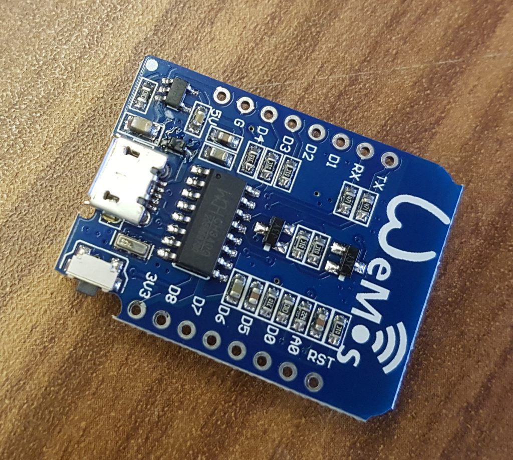
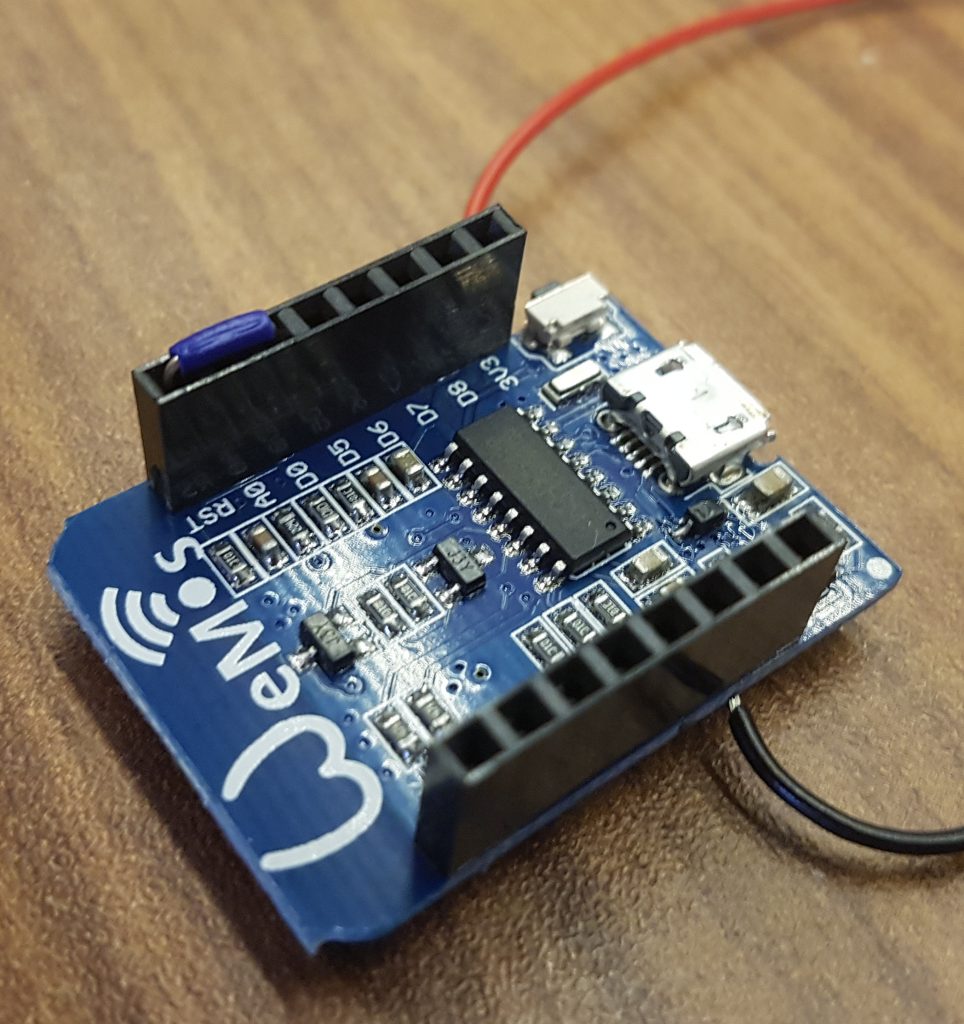
Hier der Wemos D1.mini im Detail:

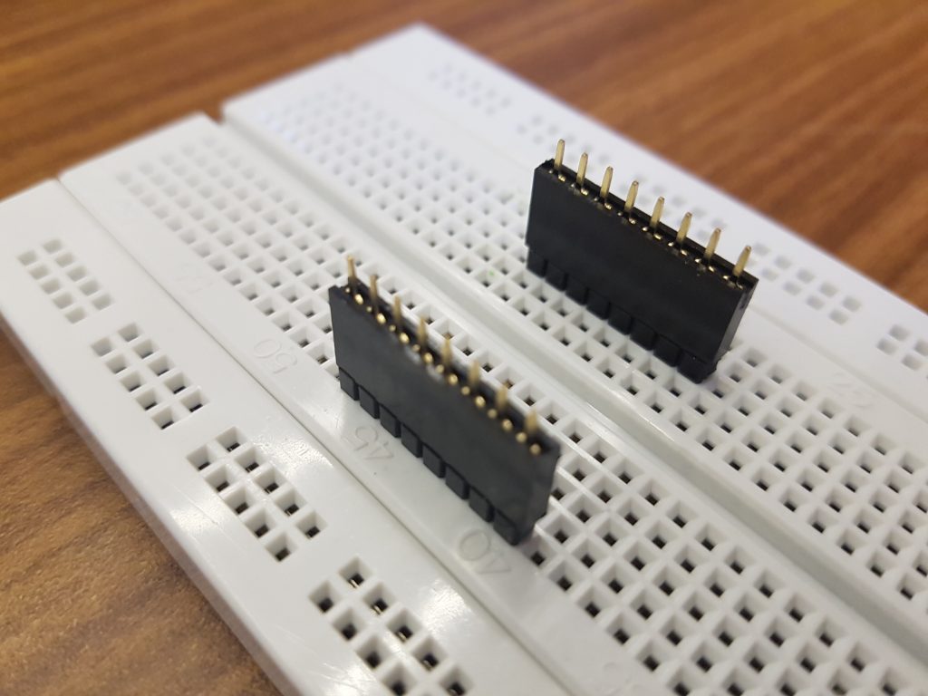
Als Trick zum einfach festlöten der Stiftleisten steckt man am besten die reinen Leisten mit den reinen Stiften umgedreht in ein Breadboard:

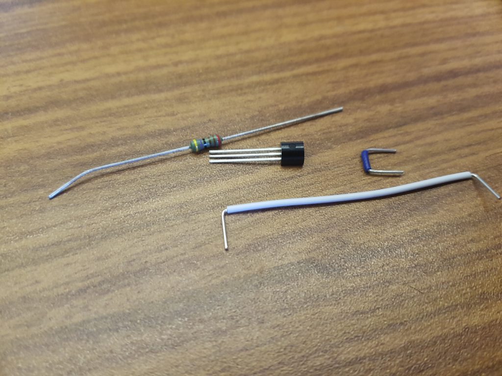
Hier noch Kabel, Temperatursensor und der Widerstand:

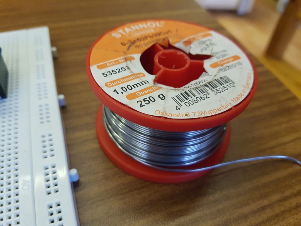
Okay ein wenig Standard-Lötzinn braucht man zum Löten doch noch:

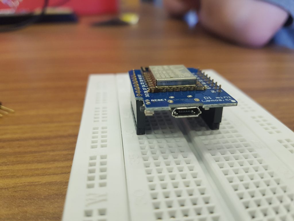
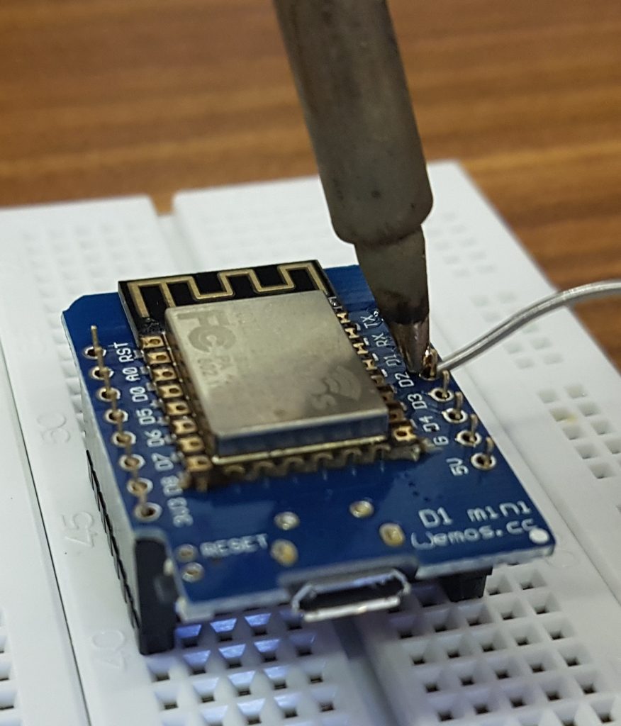
Die Stiftleisten auf den Wemos D1.mini anlöten:

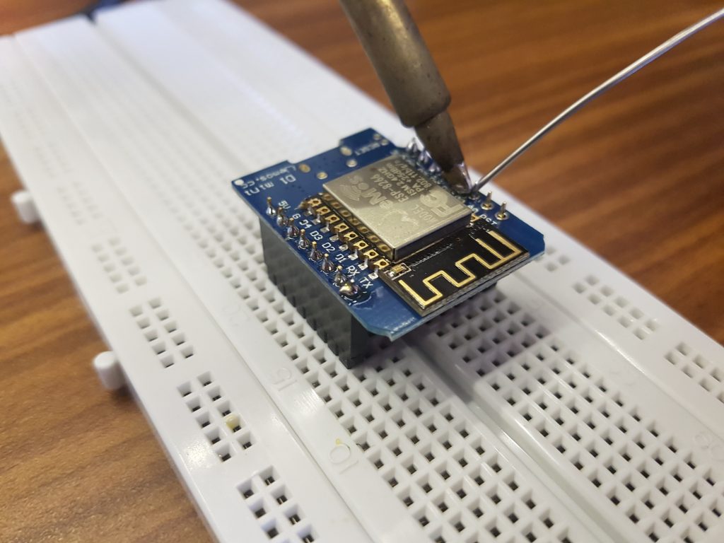
Die zweite Seite ist eigentlich optional, da nur eine Seite für den Sensor verwendet wird. Aber da wir schon mal dabei sind…

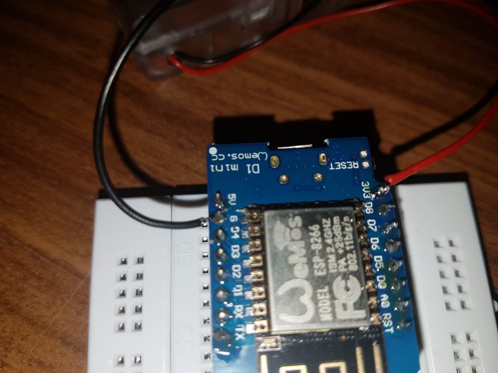
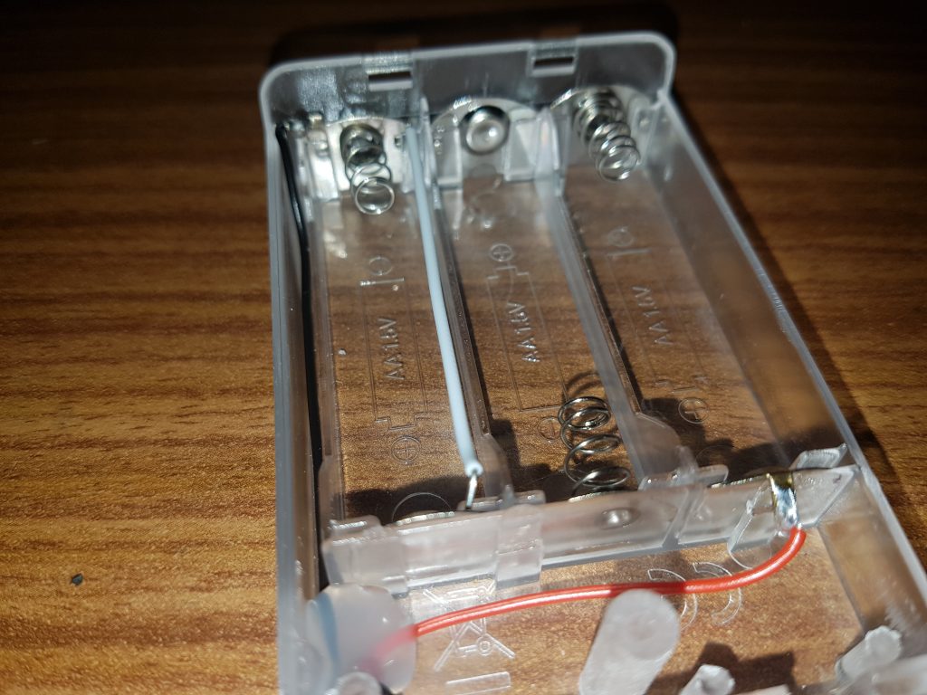
Von der Batteriebox aus muss noch die Stromversorgung angelötet werden. Dazu den nun mit den Stiftbuchsen bestückten Wemos D1.mini im Breadboard belassen und bei „3V3“ den Pluspol und bei „G“ den Minuspol anlöten.

Sofern nicht-aufladbare Batterien verwendet werden (wie in diesem Beispiel), so sollte man die Gesamtspannung bei 3 Volt belassen. Daher den dritten Batteriehalter mit einem Stück Draht überbrücken (hier in weiß). Verwendet man stattdessen Akkus, so liefern diese jeweils nur 1.2 Volt je Zelle und daher werden insgesamt 3.6 Volt benötigt. Mit 2.4 Volt wollte der ESP8266 partout nicht starten…

Damit der ESP8266 aus dem DeepSleep, in den wir ihn später schicken wollen, sich auch selbst wieder aufwecken kann, benötigt dieser noch eine Drahtbrücke zwischen D0 und RST (hier in blau). WICHTIG: Zur Programmierung muss diese Drahtbrücke wieder entfernt werden, daher diese dafür entfernen und – ganz wichtig – die Verbindung NICHT LÖTEN.

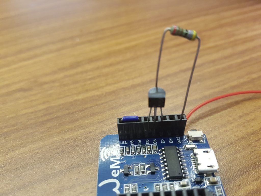
Fehlt noch der Temperatursensor selbst und ein Widerstand. Der Temperatursensor sollte mit der flachen Seite zum Chip liegen. Dann gehört das linke Bein in D5, die Mitte in D6 und das rechte Bein in D7. Nachdem man den Sensor eingesteckt hat, wird noch ein Widerstand zwischen 3V3 und dem mittleren Bein, also D6 benötigt. Dieser fungiert als „Pull-Up“ und stellt damit die Protokollfähigkeit sicher. Sollte der Sensor öfter sehr merkwürdige Werte (z.B. -127 °C) liefern, ist wahrscheinlich der Widerstand etwas herausgerutscht.

Damit der Sensor seine Daten auch verschickt, brauchen wir noch ein Programm, welches wir mit der Arduino IDE auf den ESP8266 aufspielen. Hierzu beachten, dass unter „Boards“ auch der Wemos D1.mini ausgewählt ist.

Voraussetzungen für die Arduino Umgebung:

Neueste Arduino Umgebung herunterladen und installieren (Stand Dezember 2017 ist das 1.8.5)

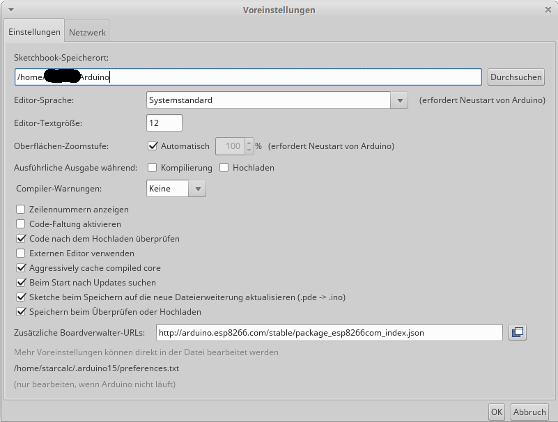
In den Voreinstellungen diese Boardverwalter-URL einfügen. Falls schon eine dort steht, kann man mit dem Knopf rechts daneben noch mehr hinzufügen.

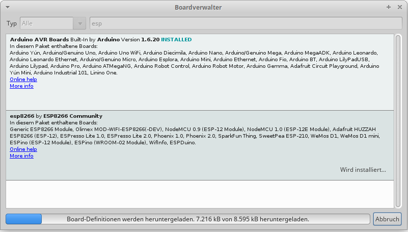
Unter Werkzeuge -> Board -> Boardverwalter (erster Eintrag) sollte man dann nach „esp“ suchen und den Eintrag ESP8266 installieren.

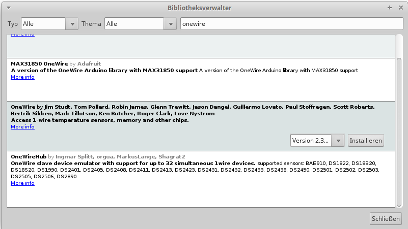
Die OneWire-Bibliothek, die wir im Programm verwenden, muss unter Sketch -> Bibliothek einbinden -> Bibliotheken verwalten hinzugefügt werden.

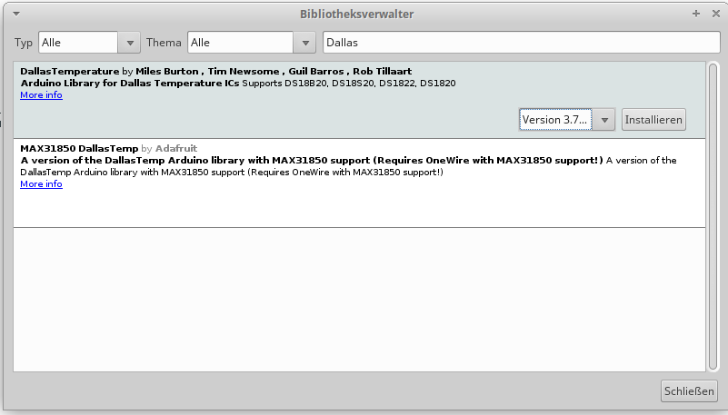
Dasselbe muss auch für die DallasTemperature-Library geschehen.

Die verwendete AsyncMQTTClient-Bibliothek gibt es leider nicht fertig in Arduino hinterlegt, hier muss die Bibliothek als ZIP-Datei hinzugefügt werden. Sketch -> Bibliothek einbinden -> .ZIP-Bibliothek einbinden.

Diese URL hinzufügen (oder alternativ jede neueres Release vom async-mqtt-client, welches auf github von marvinroger liegt).

https://github.com/marvinroger/async-mqtt-client/archive/v0.8.1.zip

Dasselbe mit der Library ESPAsyncTCP, auf welche die async-mqtt-client basiert:

https://github.com/me-no-dev/ESPAsyncTCP/archive/master.zip

Im nachfolgenden Programm müssen noch die WLAN-SSID, das WLAN-Passwort, die IP des MQTT-Servers und der Topic-„Pfad“ und ggf. der Topic-„Name“ geändert werden.

// Wemos D1 board, connected to a battery box and a DS18B20 temperature sensor
//
 
// For temperature reading
// Libraries needed:
// * OneWire
// * DallasTemperature
//
// Pinout: https://wiki.wemos.cc/products:d1:d1_mini
// D0 = GPIO16 --> Connect D0 to RST for Deep Sleep-Wakeup
 
#include <OneWire.h> 
#include <DallasTemperature.h>
 
const char* ssid = "ENTER_YOUR_SSID_HERE";
const char* password = "ENTER_YOUR_WLAN_PASS_HERE";
 
#define DEVICENAME "maintopic/devicename"
#define TOPIC DEVICENAME"/temperature"
#define ONLINETOPIC DEVICENAME"/online"
#define MQTTSERVER IPAddress(37, 187, 106, 16) // test.mosquitto.org = 37.187.106.16
const int sleepTimeS = 300; // Reduce this value for debugging. Increase if you want more battery life
 
#define VCCPIN D7
#define ONE_WIRE_BUS D6
#define GNDPIN D5
 
OneWire oneWire(ONE_WIRE_BUS); 
DallasTemperature sensors(&oneWire);
 
float tempC;
 
// For WLAN & MQTT
#include <ESP8266WiFi.h>
#include <AsyncMqttClient.h>
AsyncMqttClient mqttClient;
uint16_t packetId1Pub;
bool packet1Ack = false;
 
bool ready = false;
 
char *ftoa( double f, char *a, int precision)
{
 long p[] = {0,10,100,1000,10000,100000,1000000,10000000,100000000};
 
 char *ret = a;
 long heiltal = (long)f;
 itoa(heiltal, a, 10);
 while (*a != '\0') a++;
 *a++ = '.';
 long desimal = abs((long)((f - heiltal) * p[precision]));
 itoa(desimal, a, 10);
 return ret;
}
 
void onMqttPublish(uint16_t packetId) {
  Serial.println("** Publish acknowledged **");
  Serial.print("  packetId: ");
  Serial.println(packetId);
  if (packetId == packetId1Pub) {
    packet1Ack = true;
  }
  if (packet1Ack) {
    ready = true;
  }
}
 
void onMqttConnect(bool sessionPresent) {
  char buf[7];
  packetId1Pub = mqttClient.publish(TOPIC, 1, true, ftoa(tempC, buf, 2));
}
 
void setup() {
  pinMode(GNDPIN, OUTPUT);
  pinMode(VCCPIN, OUTPUT);
  digitalWrite(GNDPIN, LOW);
  digitalWrite(VCCPIN, HIGH);
  Serial.begin(115200); 
  Serial.println("ESP-Temperature-Reader-and-MQTT-Poster-via-WiFi"); 
  // Start up the sensors library 
  sensors.begin(); 
}
 
void loop() {
  // Send the command to get temperature readings 
  Serial.println("Requesting Temperature"); 
  sensors.requestTemperatures();
 
  // You can have more than one DS18B20 on the same bus.  
  // 0 refers to the first IC on the wire 
  Serial.println("Requesting Temperature from Device 0"); 
  tempC = sensors.getTempCByIndex(0);
 
  Serial.println("Connecting to WIFI"); 
  // Connect to WiFi
  WiFi.begin(ssid, password);
  int timeout = 0;
  while (WiFi.status() != WL_CONNECTED) {
    timeout++;
    if (timeout>20) {
        // WIFI isn't available after 10 seconds -> abort mission, mission's a failure
        initiateDeepSleep();
      }
    delay(500);
    Serial.print(".");
  }
  Serial.println("");
  Serial.println("WiFi connected");
 
  // Print the IP address
  Serial.println(WiFi.localIP());
 
  // Publish result to MQTT
  mqttClient.onConnect(onMqttConnect);
  mqttClient.onPublish(onMqttPublish);
  mqttClient.setServer(MQTTSERVER, 1883);
  mqttClient.setKeepAlive(5).setCleanSession(false).setWill(ONLINETOPIC, 2, true, "no"); // .setCredentials("user", "pass").setClientId(DEVICENAME);
  Serial.println("Connecting to MQTT...");
  mqttClient.connect();
 
  timeout = 0;
  while (!ready) {
    delay(250);
    timeout++;
    if (timeout > 40)
    {
        // MQTT isn't available after 10 seconds -> abort mission, mission's a failure
        initiateDeepSleep();
    }
    Serial.print(".");
  }
  Serial.println("");
  initiateDeepSleep();
}
 
void initiateDeepSleep()
{
  ESP.deepSleep(sleepTimeS * 1000000);
  delay(100); 
}

Die Gesamtpräsentation mit allen Informationen von dieser Webseite könnt ihr hier auch noch herunterladen:

IoT Temperatursensor Präsentation ODP

IoT Temperatursensor Präsentation PDF

Using hybrid DVB-T/DVB-C-Stick with Linux, disabling the first frontend (frontend0)

I only wanted the DVB-C-Part of my stick (dvb_usb_rtl28xxu), but after VDR access the first frontend of this device (/dev/dvb/adapter0/frontend0), the device won’t be accessible on its other frontend (/dev/dvb/adapter0/frontend1), so I had to find a way to disable the first frontend.

If you have trouble scanning any channels, please take a look at you dmesg whether there was a problem loading the correct firmware. For me it looked like this:

user@host:~# dmesg | grep firmware
[23945257.415086] mn88473 7-0018: Direct firmware load for dvb-demod-mn88473-01.fw failed with error -2

Your firmware is most certainly somewhere in the github directory of OpenELEC: https://github.com/OpenELEC/dvb-firmware/tree/master/firmware

For example, I had to copy the dvb-demod-mn88473-01.fw to /lib/firmware/:

sudo wget https://github.com/OpenELEC/dvb-firmware/raw/master/firmware/dvb-demod-mn88473-01.fw -O /lib/firmware/dvb-demod-mn88473-01.fw

Check whether w_scan works:

sudo w_scan -fc -c DE >>dvb-c-channels.conf

Search for the DEVPATH of the frontend which you want to disable (for me it was adapter0/frontend0):

user@host:~# udevadm info --query=all --name=/dev/dvb/adapter0/frontend0 | grep DEVPATH
E: DEVPATH=/devices/pci0000:00/0000:00:14.0/usb3/3-4/dvb/dvb0.frontend0

Then add a new udev-rule as a new file /etc/udev/rules.d/11-disable-frontend0.rules:

ACTION=="add", SUBSYSTEM=="dvb", ENV{DVB_DEVICE_TYPE}=="frontend", DEVPATH=="/devices/pci0000:00/0000:00:14.0/usb3/3-4/dvb/dvb0.frontend0", ENV{dynamite_attach}="no"

I must admit that this didn’t work for me. I had to move the frontend0 manually to a higher number, disabling it by this for vdr:

user@host:~# mv /dev/dvb/adapter0/frontend0 /dev/dvb/adapter0/frontend9

VDR auf Server kompilieren, Einbindung von IPTV und Steuerung über KODI auf einem Client

Server mit Netzwerkanschluss hinter einem T-Entertain-Anschluss. An den Fernsehern im Haus liegt bereits Netzwerk und jeweils ein Raspberry PI oder ähnliches, um als Empfänger des VDR-Streams zu agieren. Auf den Clients läuft ein KODI (teilweise unter OpenELEC), welcher die Integration des VDR erleichtern soll. Es steckt allerdings keine DVB-T/DVB-C-Karte oder ähnliches im Server, sondern er soll die IPTV-Streams von der Telekom (T-Entertain/T-Home) nutzen. Dieses Vorgehen ist völlig legal. Einziger Nachteil bei dieser Vorgehensweise: Es gibt praktisch keine EPG-Daten aus dem Datenstrom, diese sind – bis auf „now“ und „next“ – verschlüsselt und können nur durch den von der Telekom bereitgestellten „Media Receiver“ entschlüsselt werden.

Der VDR wurde hierfür selbst kompiliert, um die notwendigen Plugins direkt nutzen zu können. Da es einige Zeit und Nerven gekostet hat, eine vernünftige Lösung hierfür zu finden, ist hier ein Skript zu finden, welches die vorausgesetzten Pakete installiert, alles herunterlädt und kompiliert.

#!/bin/bash
 
# Work directory
### Warning: This script installs the resulting vdr to /work/vdr, yes, this is on the root level!
MYCURRENTDIR="${PWD}"
cd /work/vdr
 
#####
## Install prerequisites
#####
sudo apt-get install build-essentials dialog libcap-dev libjpeg62-dev libfreetype6{,-dev} fontconfig{,-config} libfontconfig1{,-dev} libcurl4-gnutls-dev libcxxtools-dev libtntnet-dev
 
#####
## Changes these if newer versions are available (and these work)
#####
CURRVDRVER="2.2.0"
CURRIPTVVER="2.2.1"
CURRDIR="$(pwd)"
 
#####
## Download everything which we don't already have
#####
 
if [ ! -e vdr-${CURRVDRVER}.tar.bz2 ]; then
        wget -O vdr-${CURRVDRVER}.tar.bz2 ftp://ftp.tvdr.de/vdr/vdr-${CURRVDRVER}.tar.bz2
fi
 
if [ ! -d vdr-${CURRVDRVER} ]; then
        tar xvfj vdr-${CURRVDRVER}.tar.bz2
        ln -s /work/vdr/vdr-${CURRVDRVER} /work/vdr/vdr
fi
 
if [ ! -e vdr-iptv-${CURRIPTVVER}.tgz ]; then
        wget -O vdr-iptv-${CURRIPTVVER}.tgz http://www.saunalahti.fi/~rahrenbe/vdr/iptv/files/vdr-iptv-${CURRIPTVVER}.tgz
fi
 
if [ ! -d vdr-${CURRVDRVER}/PLUGINS/src/iptv ]; then
        mkdir -p vdr-${CURRVDRVER}/PLUGINS/src/iptv
        tar xvfz vdr-iptv-${CURRIPTVVER}.tgz -C vdr-${CURRVDRVER}/PLUGINS/src/iptv --strip-components=1
fi
 
#####
## Further Plugins
#####
 
### VNSI
# https://github.com/FernetMenta/vdr-plugin-vnsiserver
if [ ! -d vdr-${CURRVDRVER}/PLUGINS/src/vdr-plugin-vnsiserver ]; then
        cd vdr-${CURRVDRVER}/PLUGINS/src
        git clone https://github.com/FernetMenta/vdr-plugin-vnsiserver
        ln -s vdr-plugin-vnsiserver vnsiserver
        cd /work/vdr
fi
 
### epgsearch (needed for VDR Live)
# http://winni.vdr-developer.org/epgsearch/downloads/vdr-epgsearch-1.0.0.tgz
if [ ! -e vdr-plugin-epgsearch-2.2.0.tgz ]; then
        wget -O vdr-plugin-epgsearch-2.2.0.tgz https://projects.vdr-developer.org/git/vdr-plugin-epgsearch.git/snapshot/vdr-plugin-epgsearch-2.2.0.tar.gz
fi
 
if [ ! -d vdr-${CURRVDRVER}/PLUGINS/src/epgsearch ]; then
        mkdir -p vdr-${CURRVDRVER}/PLUGINS/src/epgsearch
        tar xvfz vdr-plugin-epgsearch-2.2.0.tgz -C vdr-${CURRVDRVER}/PLUGINS/src/epgsearch --strip-components=1
fi
 
### VDR Live
# http://live.vdr-developer.org/downloads/vdr-live-0.3.0.tar.gz
if [ ! -e vdr-plugin-live-release_0-3-0.tgz ]; then
        wget -O vdr-plugin-live-release_0-3-0.tgz https://projects.vdr-developer.org/git/vdr-plugin-live.git/snapshot/vdr-plugin-live-release_0-3-0.tar.gz
fi
 
if [ ! -d vdr-${CURRVDRVER}/PLUGINS/src/live ]; then
        # mkdir -p vdr-${CURRVDRVER}/PLUGINS/src/live
        # tar xvfz vdr-plugin-live-release_0-3-0.tgz -C vdr-${CURRVDRVER}/PLUGINS/src/live --strip-components=1
  cd /work/vdr/vdr-${CURRVDRVER}/PLUGINS/src
        git clone https://projects.vdr-developer.org/git/vdr-plugin-live.git/
  mv /work/vdr/vdr-${CURRVDRVER}/PLUGINS/src/vdr-plugin-live /work/vdr/vdr-${CURRVDRVER}/PLUGINS/src/live
fi
 
cd /work/vdr
 
#### Autotimer
# http://phivdr.dyndns.org/vdr/vdr-autotimer/vdr-autotimer-2.3.0.tgz
if [ ! -e vdr-autotimer-2.3.0.tgz ]; then
        wget -O vdr-autotimer-2.3.0.tgz http://phivdr.dyndns.org/vdr/vdr-autotimer/vdr-autotimer-2.3.0.tgz
fi
 
if [ ! -d vdr-${CURRVDRVER}/PLUGINS/src/vdr-autotimer ]; then
        mkdir -p vdr-${CURRVDRVER}/PLUGINS/src/autotimer
        tar xvfz vdr-autotimer-2.3.0.tgz -C vdr-${CURRVDRVER}/PLUGINS/src/autotimer --strip-components=1
fi
 
#####
## Compile
#####
 
cd /work/vdr/vdr-${CURRVDRVER}
# Das CXXFLAGS="-std=gnu++03" wird benoetigt, da das iptv-Plugin mit den neuen Makros nicht klar kommt (-std=gnu11)
CXXFLAGS="-std=gnu++03" make -j $(grep -c ^processor /proc/cpuinfo)
cd ..
 
# channels.conf (loading these from a forum where someone listed all channels...)
if [ ! -e channels.conf ]; then
  preString = "pre" # Workaround for wordpress-blogpost, it would end the code otherwise
  wget -O - -q  http://www.vdr-portal.de/board16-video-disk-recorder/board5-vdr-konfiguration/119211-iptv-t-home-entertain-channels-conf-aktuelle-eintr%C3%A4ge/ | grep "\(IPTV:\|</${prestring}>\)" | sed '1,1d; /<\/pre>/,$d' >channels.conf
fi
cd /work/vdr/vdr-${CURRVDRVER}
rm channels.conf
ln -s ../channels.conf channels.conf
 
mkdir -p video
mkdir -p resources
mkdir -p cache
 
# Webinterface
sudo ln -s /work/vdr/vdr/PLUGINS/src/live/live/css /work/vdr/vdr-2.2.0/resources/plugins/live/
sudo ln -s /work/vdr/vdr/PLUGINS/src/live/live/img /work/vdr/vdr-2.2.0/resources/plugins/live/
sudo ln -s /work/vdr/vdr/PLUGINS/src/live/live/js /work/vdr/vdr-2.2.0/resources/plugins/live/
sudo ln -s /work/vdr/vdr/PLUGINS/src/live/live/themes /work/vdr/vdr-2.2.0/resources/plugins/live/
 
# setup.conf initial
## sudo rm /work/vdr/vdr-${CURRVDRVER}/setup.conf
 
# iptv configuration
# 15.07.2014: Sollte der VDR die IPTV Kanäle mit der CAID "4AE2" versehen, im iptv-Plugin "Deaktiviere Filter: 1 (PAT 0x00)" definieren und Einträge bereinigen
sudo bash -c "cat <<EOF >>setup.conf
iptv.DisabledFilters = 1
EOF
"
 
# vnsiserver configuration
sudo mkdir -p /media/tv
 
sudo bash -c "cat <<EOF >>setup.conf
vnsiserver.Timeshift = 2
vnsiserver.TimeshiftBufferDir = /media/tv
vnsiserver.TimeshiftBufferFileSize = 20
vnsiserver.TimeshiftBufferSize = 30
EOF
"
 
 
# vnsiserver access rights
# sudo cat >/work/vdr/vdr-${CURRVDRVER}/plugins/vnsiserver/allowed_hosts.conf <<EOF
sudo bash -c "cat <<EOF >/work/vdr/vdr/plugins/vnsiserver/allowed_hosts.conf
#
# allowed_hosts.conf  This file describes a number of host addresses that
#                     are allowed to connect to the streamdev server running
#                     with the Video Disk Recorder (VDR) on this system.
# Syntax:
#
# IP-Address[/Netmask]
#
 
127.0.0.1             # always accept localhost
192.168.6.0/24        # any host on the local net
#204.152.189.113      # a specific host
#0.0.0.0/0            # any host on any net (USE THIS WITH CARE!)
EOF
"
 
# Plugins
cd PLUGINS/lib
rm *
 
find ../ -iname '*.so' -exec ln -s {} . \;
for file in *.so; do mv ${file} $(echo ${file} | sed "s/\.so/.so.${CURRVDRVER}/") ; done
 
cd ../..
 
echo "Starting VDR"
cd ..
echo "Going back to ${MYCURRENTDIR}"
cd "${MYCURRENTDIR}"
 
./run.sh

And for run.sh, I used this:

#!/bin/bash
cd /work/vdr/vdr && sudo /work/vdr/vdr/vdr --log=3 -v /data/Videos/TV -c . -L /work/vdr/vdr/PLUGINS/lib --plugin=iptv --localedir=/work/vdr/vdr/locale --resdir=/work/vdr/vdr/resources --cachedir=/work/vdr/vdr/cache -P'vnsiserver -t 5' -P'epgsearch' -P'live'

Mining Monero on old Ubuntu

Getting the xmr-stak-cpu to work on an ubuntu 14.04:

* Compile gcc from scratch and install to /home/user/inst (script)

#!/bin/bash
VER=7.2.0
cd
WORKDIR=${PWD}/work/gcc-${VER}
INSTDIR=${PWD}/inst
mkdir -p ${WORKDIR}
mkdir -p ${INSTDIR}
cd ${WORKDIR}
if [ ! -e gcc-${VER}.tar.gz ]; then
	wget -O gcc-${VER}.tar.gz ftp://ftp.gwdg.de/pub/misc/gcc/releases/gcc-${VER}/gcc-${VER}.tar.gz
fi
if [ ! -e gcc-${VER} ]; then
	tar xvfz gcc-${VER}.tar.gz
fi
cd gcc-${VER}
./contrib/download_prerequisites
# 64bit only
./configure --disable-multilib --prefix=${INSTDIR} && make -j $(grep -c ^processor /proc/cpuinfo) && make install

* Compile cmake from scratch

cd
INSTDIR=${PWD}/inst
mkdir -p work
cd work
mkdir -p cmake
cd cmake
wget https://cmake.org/files/v3.9/cmake-3.9.3.tar.gz
tar xvfz cmake-3.9.3.tar.gz
cd cmake-3.9.3
CC=${INSTDIR}/bin/gcc CXX=${INSTDIR}/bin/g++ PATH=${INSTDIR}/bin:$PATH ./configure --prefix=${INSTDIR} && LD_LIBRARY_PATH="$HOME/inst/lib64" make -j $(grep -c ^processor /proc/cpuinfo) && LD_LIBRARY_PATH="$HOME/inst/lib64" make install

* Download the xmr-stak-cpu files and compile

cd
INSTDIR=${PWD}/inst
mkdir -p $HOME/work/xmr
cd $HOME/work/xmr
git clone https://github.com/fireice-uk/xmr-stak-cpu
cd xmr-stak-cpu
LD_LIBRARY_PATH="$HOME/inst/lib64" CC=${INSTDIR}/bin/gcc CXX=${INSTDIR}/bin/g++ PATH=${INSTDIR}/bin:$PATH cmake . -DCMAKE_INSTALL_PREFIX=$HOME/xmr-stak-cpu -DMICROHTTPD_REQUIRED=OFF && LD_LIBRARY_PATH="$HOME/inst/lib64" make && LD_LIBRARY_PATH="$HOME/inst/lib64" make install

This will compile the file with the new gcc and the new cmake. The result will be installed to $HOME/xmr-stak-cpu, it’s only the executable file and the config.txt.

To run, you must point your LD_LIBRARY_PATH to the correct directory, otherwise you’ll get strange errors:

LD_LIBRARY_PATH="$HOME/inst/lib64" ./xmr-stak-cpu

Arduino als JTAG Programmer

Ich würde gerne meine Honeywell Heizkörperregler HR-20 Rondostat zeitgesteuert nicht nur passiv auslesen (das geht auch schon mit der nativen Firmware), sondern auch über einen ESP8266 steuern. Das wurde schon von schlauen Leuten vorgedacht, und daher gibt es mit OpenHR20 auch eine neue Firmware, welche man mittels JTAG-Interface auf das HR20 flashen kann.

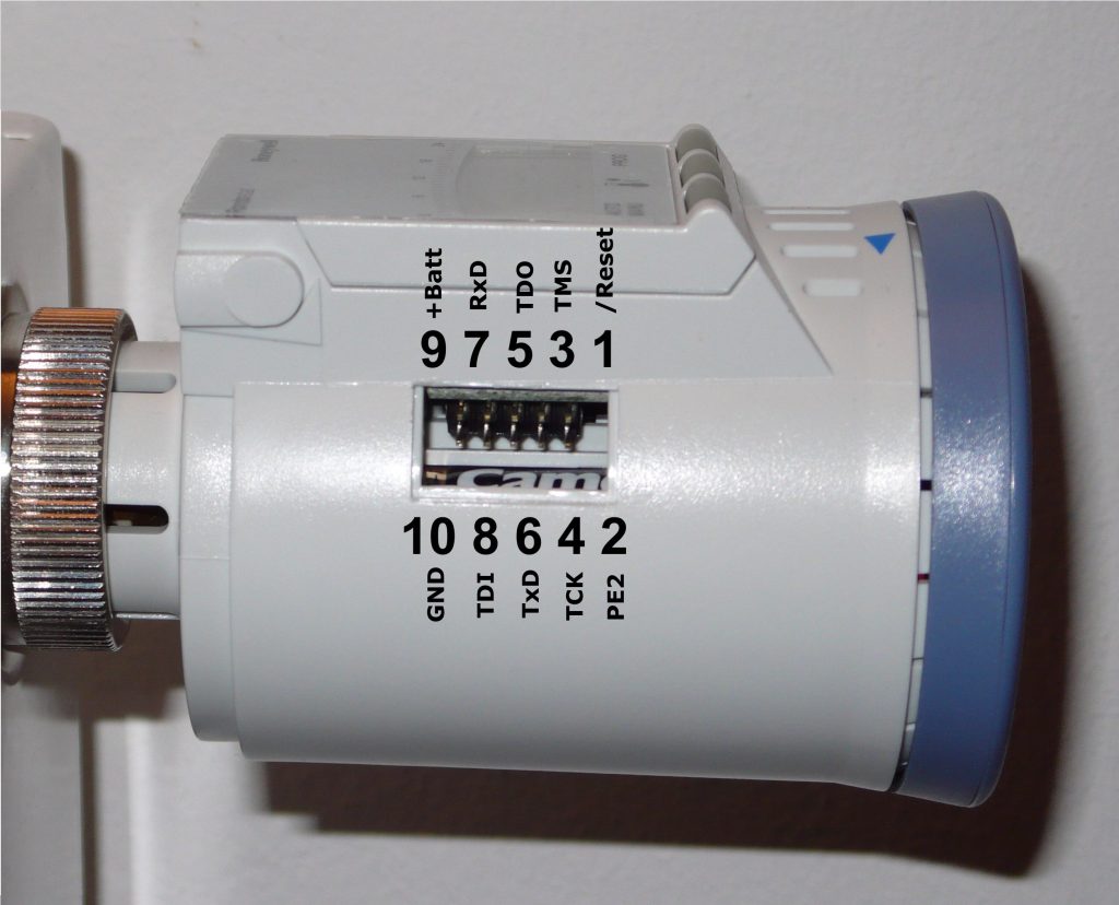
Ich habe nur kein JTAG-Programmierer zur Hand, aber dafür einen Arduino Uno. Ich habe den Ansatz eines JTAGduino gefunden. Die notwendigen Lötarbeiten waren schnell erledigt, ich habe die nachfolgende Steckerbelegung (Quelle) berücksichtigt, um den JTAGduino zu versorgen. Um eine durchgehende Stiftleiste am Arduino Uno verwenden zu können, habe ich die gesamte Kommunikation auf die Analogen Ports A0 bis A4 gelegt.

Die ersten Tests mit den von JTAGduino mitgelieferten Skripten verliefen erfolgreich, wenn ich das JTAG-Interface vom Arduino an den HR20 angeschlossen habe und mein Arduino an meinen Linux-Rechner per USB verbunden ist, kommt folgende Ausgabe:

user@host:~/work/JTAGduino$ ./host_test.py 
if_ver_major = 0; if_ver_minor = 1
fw_ver_major = 0; fw_ver_minor = 1
set_serial_speed(115200) = 0
clear pin TDI rsp = 1
set pin TDI rsp = 0
get pin TDO rsp = 0; val = 0
jtag_clock(1,1): rsp = 1; tdo = 0
jtag_clock(1,0): rsp = 0; tdo = 1
jtag_sequence([1,1,1,1], [1, 1, 0, 1]), rsp = 0; tdo_seq = [1, 0, 0, 0]
jtag_sequence([1] * 255, [1] * 255), rsp = 0; tdo_seq = [1, 1, 1, 1, 0, 0, 0, 0, 0, 0, 0, 0, 0, 0, 0, 0, 1, 1, 1, 1, 1, 1, 1, 1, 1, 1, 1, 1, 1, 1, 1, 1, 1, 1, 1, 1, 1, 1, 1, 1, 1, 1, 1, 1, 1, 1, 1, 1, 1, 1, 1, 1, 1, 1, 1, 1, 1, 1, 1, 1, 1, 1, 1, 1, 1, 1, 1, 1, 1, 1, 1, 1, 1, 1, 1, 1, 1, 1, 1, 1, 1, 1, 1, 1, 1, 1, 1, 1, 1, 1, 1, 1, 1, 1, 1, 1, 1, 1, 1, 1, 1, 1, 1, 1, 1, 1, 1, 1, 1, 1, 1, 1, 1, 1, 1, 1, 1, 1, 1, 1, 1, 1, 1, 1, 1, 1, 1, 1, 1, 1, 1, 1, 1, 1, 1, 1, 1, 1, 1, 1, 1, 1, 1, 1, 1, 1, 1, 1, 1, 1, 1, 1, 1, 1, 1, 1, 1, 1, 1, 1, 1, 1, 1, 1, 1, 1, 1, 1, 1, 1, 1, 1, 1, 1, 1, 1, 1, 1, 1, 1, 1, 1, 1, 1, 1, 1, 1, 1, 1, 1, 1, 1, 1, 1, 1, 1, 1, 1, 1, 1, 1, 1, 1, 1, 1, 1, 1, 1, 1, 1, 1, 1, 1, 1, 1, 1, 1, 1, 1, 1, 1, 1, 1, 1, 1, 1, 1, 1, 1, 1, 1, 1, 1, 1, 1, 1, 1, 1, 1, 1, 1, 1, 1, 1, 1, 1, 1, 1, 1, 1, 1, 1, 1, 1, 1]
device.set_jtag_speed(1) = 255
jtag_sequence([1] * 255, [1] * 255), rsp = 127; tdo_seq = []
user@host:~/work/JTAGduino$ ./readid.py 
Traceback (most recent call last):
  File "./readid.py", line 81, in 
    if rsp != 0: raise Exception('error: set_jtag_speed returned %d' % rsp)
Exception: error: set_jtag_speed returned 191
user@host:~/work/JTAGduino$ ./readid.py 
#Taps = 1
Device identifier registers (beginning from closest to TDO):
0x6940503F

Die Fehlermeldung habe ich absichtlich drin gelassen, damit man auch andere den Grund für den Fehler finden können. Man muss vor JEDEM Ansprechen des JTAGduino diesen manuell auf durch einen Druck auf den Reset-Button am Arduino zurücksetzen.

Die ID 0x6940503F ist bereits die vom HR20, wir können also grundsätzlich per JTAG bereits mit ihm kommunizieren.

Als nächstes muss ich noch herausfinden, wie avrdude mit dem so gebauten „Programmer“ sprechen kann, bisher habe ich nur ermitteln können, dass es eine mögliche Liste von Programmern in avrdude vordefiniert gibt: (Der Pfad zur Arduino-Installation muss natürlich angepasst werden)

user@host:~/work/JTAGduino$ PATH=$PATH:/arduino-1.8.1/hardware/tools/avr/bin avrdude -c dslfkj -C /arduino-1.8.1/hardware/tools/avr/etc/avrdude.conf 2&lt;&amp;1 | grep -i jtag
  atmelice         = Atmel-ICE (ARM/AVR) in JTAG mode (avrdude: jtag3_open_common(): JTAGICE3/EDBG port names must start with "usb")
  dragon_jtag      = Atmel AVR Dragon in JTAG mode
  jtag1            = Atmel JTAG ICE (mkI)
  jtag1slow        = Atmel JTAG ICE (mkI)
  jtag2            = Atmel JTAG ICE mkII
  jtag2avr32       = Atmel JTAG ICE mkII im AVR32 mode
  jtag2dw          = Atmel JTAG ICE mkII in debugWire mode
  jtag2fast        = Atmel JTAG ICE mkII
  jtag2isp         = Atmel JTAG ICE mkII in ISP mode
  jtag2pdi         = Atmel JTAG ICE mkII PDI mode
  jtag2slow        = Atmel JTAG ICE mkII
  jtag3            = Atmel AVR JTAGICE3 in JTAG mode
  jtag3dw          = Atmel AVR JTAGICE3 in debugWIRE mode
  jtag3isp         = Atmel AVR JTAGICE3 in ISP mode
  jtag3pdi         = Atmel AVR JTAGICE3 in PDI mode
  jtagkey          = Amontec JTAGKey, JTAGKey-Tiny and JTAGKey2
  jtagmkI          = Atmel JTAG ICE (mkI)
  jtagmkII         = Atmel JTAG ICE mkII
  jtagmkII_avr32   = Atmel JTAG ICE mkII im AVR32 mode
  o-link           = O-Link, OpenJTAG from www.100ask.net (avrdude: Error: no libftdi or libusb support. Install libftdi1/libusb-1.0 or libftdi/libusb and run configure/make again.)
  xil              = Xilinx JTAG cable (tested - avrdude: can't claim device "/dev/ttyACM0": Inappropriate ioctl for device)
  xplainedpro      = Atmel AVR XplainedPro in JTAG mode

Den nachfolgenden Befehl nutze ich zum Test, ob der jeweilige Programmer-Typ funktioniert, er sollte bei erfolgreicher Kommunikation nur Backups von fuses anlegen, also führt noch keine schreibenden Operationen aus:

user@host:~/work/JTAGduino$ PATH=$PATH:/arduino-1.8.1/hardware/tools/avr/bin avrdude -p m169 -c xil -P /dev/ttyACM0 -C /arduino-1.8.1/hardware/tools/avr/etc/avrdude.conf -U lfuse:r:backup/unknown/`date  "+%F_%T"`/lfuse.hex:h -U hfuse:r:backup/unknown/`date  "+%F_%T"`/hfuse.hex:h -U efuse:r:backup/unknown/`date  "+%F_%T"`/efuse.hex:h

So wie es aussieht, ist die Library nicht komplett, und für meinen Anwendungszweck vielleicht gar nicht geeignet. Ich bin dadurch über eine JTAG-Library gestoßen, welche man direkt über die Arduino-IDE nachinstallieren kann: https://github.com/mrjimenez/JTAG

Nach dem Upload des JTAGTest-Programms (wird als Beispiel in der ArduinoIDE bereitgestellt, wenn man die Bibliothek installiert hat) auf dem Arduino kann man das python-Programm „xsvf“ nutzen, um erste Tests durchzuführen:

user@host:~/work/JTAG/extras/python$ ./xsvf ../xsvf/all/idcode_simpler.xsvf
File: /work/JTAG/extras/xsvf/all/idcode_simpler.xsvf
Ready to send 18 bytes.
Sent:       18 bytes,        0 remaining
IMPORTANT: ********
IMPORTANT: Success!
IMPORTANT: ********
IMPORTANT: Last TDO: FF FF FF FF/32 bits
IMPORTANT: Processed 5 instructions.
IMPORTANT: Checksum:  0xC2/18.
IMPORTANT: Sum: 0x0000003E/18.
Quit: No error (0).
  Expected checksum:  0xC2/18.
  Expected sum: 0x0000003E/18.
Elapsed time: 0.02 seconds.

Mit der neuen JTAG-Library alle möglichen Programmiermodi des avrdude durchgegangen:

atmelice         = Atmel-ICE (ARM/AVR) in JTAG mode (avrdude: jtag3_open_common(): JTAGICE3/EDBG port names must start with "usb")
  dragon_jtag      = Atmel AVR Dragon in JTAG mode (no response)
  jtag1            = Atmel JTAG ICE (mkI) (avrdude: jtagmkI_open(): failed to synchronize to ICE)
  jtag1slow        = Atmel JTAG ICE (mkI) (avrdude: jtagmkI_open(): failed to synchronize to ICE)
  jtag2            = Atmel JTAG ICE mkII (no response)
  jtag2avr32       = Atmel JTAG ICE mkII im AVR32 mode (avrdude: jtagmkII_recv_frame(): timeout     avrdude: jtagmkII_getsync(): sign-on command: status -1)
  jtag2dw          = Atmel JTAG ICE mkII in debugWire mode
  jtag2fast        = Atmel JTAG ICE mkII
  jtag2isp         = Atmel JTAG ICE mkII in ISP mode
  jtag2pdi         = Atmel JTAG ICE mkII PDI mode
  jtag2slow        = Atmel JTAG ICE mkII
  jtag3            = Atmel AVR JTAGICE3 in JTAG mode
  jtag3dw          = Atmel AVR JTAGICE3 in debugWIRE mode
  jtag3isp         = Atmel AVR JTAGICE3 in ISP mode
  jtag3pdi         = Atmel AVR JTAGICE3 in PDI mode
  jtagkey          = Amontec JTAGKey, JTAGKey-Tiny and JTAGKey2
  jtagmkI          = Atmel JTAG ICE (mkI)
  jtagmkII         = Atmel JTAG ICE mkII
  jtagmkII_avr32   = Atmel JTAG ICE mkII im AVR32 mode
  o-link           = O-Link, OpenJTAG from www.100ask.net (avrdude: Error: no libftdi or libusb support. Install libftdi1/libusb-1.0 or libftdi/libusb and run configure/make again.)
  xil              = Xilinx JTAG cable (avrdude: can't claim device "/dev/ttyACM0": Inappropriate ioctl for device)
  xplainedpro      = Atmel AVR XplainedPro in JTAG mode (avrdude: jtag3_open_common(): JTAGICE3/EDBG port names must start with "usb")


Arduino als Audio-Aufnahmequelle

Ich habe einen der Mikrofon-Sensoren ergattert, die man für Arduino bzw. Raspberry Pis günstig erwerben kann. Meiner war in einem „37 in 1“-Sensor-Kit enthalten. Schließt man diesen direkt mit A0 an den Arduino an, erhält man allerdings keine sinnvollen Werte, insbesondere weichen diese kaum von 2.5V Eingang ab. Die prinzipielle Schaltung lässt aber auf „D0“ das High bzw. Low erkennen, der Sensor selbst funktioniert also.

Um sinnvoll damit arbeiten zu können, musste ich zunächst einmal den Ausgang entkoppeln, dafür habe ich einen kleinen Kondensator (4.7 uF) angeschlossen. Das aus dem A0-Anschluss dieses Mikrofon-Breakouts erhaltene Signal ist nur zu schwach, muss also deutlich verstärkt werden. Ich habe einen MAX406 gefunden, der herumlag. Mit 470 Ohm als Vorwiderstand und 100 kOhm als Widerstand zwischen IN- und OUT sollte eine etwa 25-fache-Verstärkung herauskommen.

Das Signal aus dem Mikrofon komm ebenfalls an IN-, an IN+ habe ich GND angeschlossen.

Mit einem Piezo-Lautsprecher angeschlossen an GND und PIN9 vom Arduino Uno und das verstärkte Eingangssignal an A0 kann man nun gute das „Knackern“ hören, was vorher nur ein unangenehmes Piepsen war. Im seriellen Output kann man gut nachvollziehen, dass von der Schwallwelle nur eine Seite der Welle verstärkt wird, die andere ist praktisch immer Null und somit kommt auch noch nicht wirklich etwas verständliches heraus. Immerhin sind einfach Testtöne (Sinus-Wellen) darüber schon zu erkennen.

Ein möglicher nächster Schritt wäre nun:

Über einen (einstellbaren) Spannungsteiler die Referenzspannung, die an IN+ gegeben wird, zu verkleinern. Ferner muss das Eingangssignal durch einen 1:1-Spannungsteiler geschickt werden, um dann bei „keinem“ Signal etwa 50% Ausgangssignal zu liefern und dies dann beim Arduino wieder herauszurechnen. So würde das Signal vollständig verstärkt werden.

WinPCap in eigenem .NET-Programm verwenden

Den letzten „Developer’s Pack“ von WinPCap herunterladen:

http://www.winpcap.org/devel.htm

Auspacken und die Location merken, wo die Dateien nun liegen.

Wrapper herunterladen:

https://github.com/PcapDotNet/Pcap.Net/tree/master

Am einfachsten hierzu das aktuelle Repository als ZIP-Datei herunterladen und entpacken:

https://github.com/PcapDotNet/Pcap.Net/archive/master.zip

In dem ausgepackten Pfad diese Solution öffnen:

Pcap.Net-master\PcapDotNet\src\PcapDotNet.sln

  • Auf „Release“ umstellen
  • Auf „x64“ umstellen
  • PcapDotNet.Core -> Rechtsklick -> Eigenschaften
    • VC++ Directories
      • Include Directories: Den Pfad vom WpdPack\Include hinzufügen
      • Library Directories: Den Pfad von WpdPack\Lib\x64 hinzufügen
  • Alles kompilieren (Das Target Framework muss identisch mit dem im nächsten Schritt verwendeten sein)

Testweise etwas kompilieren:

Pcap.Net-master\PcapDotNet.DevelopersPack\src\PcapDotNet.DevelopersPack.sln öffnen

Bei „ObtainingTheDeviceList“ muss man die References anpassen, die Pfade müssen auf die „Relase“-Zweige der oben erstellten DLLs zeigen.

Das Resultat sollte ein Kommandozeilenfenster mit „1. rpcap://\Device…“ sein.

Export EV3 from Lego Digital Designer

Recently I created a complex LEGO model with Lego Digital Designer and wanted to import the resulting model into Blender. My export files were missing the LEGO Mindstorms EV3-components that I had added.

The reason for this behaviour are the missing parts in the ldraw.xml-File, which is in the same directory as the ldd.exe, the directory C:\Program Files (x86)\LEGO Company\LEGO Digital Designer held this file for me.

The ldraw.xml is essentially a mapping file, which maps all the LEGO-internal structures to the more open „LDRAW“-File format. The EV3-parts weren’t listed and even in updated ldraw.xml-Files, which I could find on the web, these were never added.

So I created the missing mappings on my own and the result works pretty good. Not all the colours are correct, but I couldn’t find an easy way to correct these.

Here are the necessary steps to successfully export LEGO EV3-parts from Lego Digital Designer and import these with correct colours e.g. into Blender:

  1. Copy ldraw.xml file to your location of ldd.exe, overwrite the old ldraw.xml. (Unzip the ldraw.zip to ldraw.xml first)
  2. Export your model from Lego Digital Designer to „LDraw-Files (*.ldr)“-format.
  3. Open the file in notepad++, search for the following part numbers (they are located at the end of the line) and change the BEGINNING of the line from „1 71“ to „1 15“.
    • Example:
      • 1 71 -90.175277709960937 -176.40634155273437 -275.99981689453125 0 1.0000001192092896 0 0 0 1.0000001192092896 1.0000001192092896 0 0 95658.dat
      • 1 15 -90.175277709960937 -176.40634155273437 -275.99981689453125 0 1.0000001192092896 0 0 0 1.0000001192092896 1.0000001192092896 0 0 95658.dat
    • Do this for all lines with these part numbers (not all might be in your file, only if you have added the corresponding EV3-bricks):
      • 95650.DAT
      • 95658.DAT
      • 95648.DAT
      • 99455.DAT
  4. Import the corrected file in LeoCAD and export into „Wavefront (.obj)“
  5. Open Blender and follow these instructions to get a first decent result:
    1. File -> Import -> Wavefront (.obj)
    2. Select -> Select all by Type -> Mesh
    3. Press „s“ (SCALE) and enter a value (blind, there is no dialog box), e.g. „0.1“ and hit return. Or you resize with your mouse after pressing „s“.
    4. Right-click and hold on the camera in blender, and move it around to where you want it to be.
    5. Check your current view by hitting the „0“ on your numpad. (This will change to the camera view)
    6. Right-Click during camera view on the border of the camera (it will turn orange), and then right-click and hold outside the camera view to tilt for your needs.
    7. Add some lights via Add -> Lamp -> Area  (or Sun) and position them.
    8. Render by pressing F12
    9. In the render-menu on the right hand side you can change the size of the resulting image, e.g. „Preset: HDTV 1080p“.
    10. By pressing F3 the rendered image is stored to your disc. (Current used path is at the bottom of the render-menu, defaults to /tmp.)

KODI: Spinup HDD when Screensaver was deactivated

When trying to access my recordings on my NAS, kodi seems to stop working for a short while when the NAS realizes that it is being accessed and starts spinning up the discs. I figured that it would be nice for the NAS to spin up earlier, if the screen saver of a „connected KODI“ is deactivated.

After enabling the JSON-RPC-TCP 9090-Port on Kodi (In System/Settings/Network/Services activate „Allow programs on this system to control Kodi for localhost access only“ and „Allow programs on other systems to control Kodi for access from other computers as well“), this script should be run at boottime on the NAS. Make sure to replace the accessed discs with your /dev/sdX-entries on your system. Also replace HOSTNAME with the host which as Kodi running, if the discs are in use on the same host, replace it with „localhost“.

The command must be run as root.

onidlespinupdiscs.sh:

#!/bin/bash
# Must be run as root
while true
do
  netcat -d HOSTNAME 9090 | (
    cnt=0
    line=
    while read -N 1 c; do
      line="$line$c"
      if [ "$c" = "{" ]; then
        cnt=$((cnt+1))
      elif [ "$c" = "}" ]; then
        cnt=$((cnt-1))
        if [ $cnt -eq 0 ]; then
          printf "%s\n" "$line"
          line=
        fi
      fi
    done
  ) | while read line
  do
    match=$(echo ${line} | grep -c "GUI.OnScreensaverDeactivated")
    if [ $match -eq 1 ]; then
      dd if=/dev/sdb bs=4096 count=1 of=/dev/null iflag=direct >/dev/null 2>&1 &
      dd if=/dev/sdc bs=4096 count=1 of=/dev/null iflag=direct >/dev/null 2>&1 &
    fi
  done
  sleep 60
done

Disable all LEDs and network LEDs on Raspberry Pi 2 with OpenELEC

I’m using OpenELEC on a Raspberry Pi 2, but the LEDs, especially those of the network device, are WAY too bright and keep distracting people when watching TV. The LEDs which are onboard of the RPi2 can be disabled with two simple commands (see below), but the network lights are much brighter and can’t be disabled by default.

I found a website which was written in portoguese, which offered a patch for this problem. The patch didn’t work with the current OpenELEC-release, so I had to modify it a bit.

Simply put, the patch adds a new functionality to the driver for the network interface smsc95xx.c, by creating three sysfs-entries.

Here is the modified patch, to apply it, you have to git clone the current OpenELEC-github-Repository and copy the patch to this directory: /OpenELEC.tv/packages/linux/patches/

File linux-999-disable-network-lights.patch:

--- a/drivers/net/usb/smsc95xx.c
+++ b/drivers/net/usb/smsc95xx.c
@@ -74,6 +74,8 @@
 module_param(turbo_mode, bool, 0644);
 MODULE_PARM_DESC(turbo_mode, "Enable multiple frames per Rx transaction");
 
+int smsc95xx_ledctl(struct usbnet *dev);
+
 static int __must_check __smsc95xx_read_reg(struct usbnet *dev, u32 index,
                                            u32 *data, int in_pm)
 {
@@ -1024,6 +1026,9 @@
        if (ret < 0)
                return ret;
 
+       // Init sysfs led controller
+       smsc95xx_ledctl(dev);
+
        /* Init Tx */
        ret = smsc95xx_write_reg(dev, FLOW, 0);
        if (ret < 0)
@@ -2023,3 +2028,87 @@
 MODULE_AUTHOR("Steve Glendinning <steve.glendinning@shawell.net>");
 MODULE_DESCRIPTION("SMSC95XX USB 2.0 Ethernet Devices");
 MODULE_LICENSE("GPL");
+
+/*
+ * Led control patch
+ */
+
+static struct usbnet *leddev = NULL;
+
+static ssize_t smsc95xx_store(struct class *cls, struct class_attribute *attr, const char *buf, size_t count);
+static ssize_t smsc95xx_show(struct class *cls, struct class_attribute *attr, char *buf);
+
+static CLASS_ATTR(eth_fdx,S_IWUSR, smsc95xx_show, smsc95xx_store);
+static CLASS_ATTR(eth_lnk,S_IWUSR, smsc95xx_show, smsc95xx_store);
+static CLASS_ATTR(eth_spd,S_IWUSR, smsc95xx_show, smsc95xx_store);
+
+int smsc95xx_ledctl(struct usbnet *dev){
+
+    int ret = 0;
+    static struct class led_gpio = {
+
+        .name = "smsc95xx_leds",
+    };
+
+    if(leddev != NULL) return 0;
+
+    leddev = dev;
+
+    ret = class_register(&led_gpio);
+    if(ret){
+        leddev = NULL;
+        return ret;
+    }
+
+    ret += class_create_file(&led_gpio,&class_attr_eth_fdx);
+    ret += class_create_file(&led_gpio,&class_attr_eth_lnk);
+    ret += class_create_file(&led_gpio,&class_attr_eth_spd);
+
+    if(ret){
+        leddev = NULL;
+        class_unregister(&led_gpio);
+        return ret;
+    }
+
+    return 0;
+}
+
+static ssize_t smsc95xx_show(struct class *cls, struct class_attribute *attr, char *buf){
+
+return scnprintf(buf, PAGE_SIZE, "you can't even read");
+}
+
+
+static ssize_t smsc95xx_store(struct class *cls, struct class_attribute *attr, const char *buf, size_t count){
+int ret = 0;
+static u32 write_buf = LED_GPIO_CFG_FDX_LED |
+                       LED_GPIO_CFG_LNK_LED |
+                       LED_GPIO_CFG_SPD_LED;
+
+
+    if(buf[0] == '0'){
+
+        switch(attr->attr.name[6]){
+
+            case 'x': write_buf ^= LED_GPIO_CFG_FDX_LED; break;
+            case 'k': write_buf ^= LED_GPIO_CFG_LNK_LED; break;
+            case 'd': write_buf ^= LED_GPIO_CFG_SPD_LED; break;
+        }
+
+    }else if(buf[0] == '1'){
+
+        switch(attr->attr.name[6]){
+
+            case 'x': write_buf |= LED_GPIO_CFG_FDX_LED; break;
+            case 'k': write_buf |= LED_GPIO_CFG_LNK_LED; break;
+            case 'd': write_buf |= LED_GPIO_CFG_SPD_LED; break;
+        }
+    }
+
+    ret = smsc95xx_write_reg(leddev, LED_GPIO_CFG, write_buf);
+
+    if(ret < 0) netdev_warn(leddev->net,"Failed to write LED_GPIO_CFG: %d\n",ret);
+
+    return 1;
+}
+

If the file is correctly copied, you can start to build the image, this will take some time:

PROJECT=RPi2 ARCH=arm make image

Copy the new image to a fresh sd-card and insert it into the RPi2. After boot, connect to ssh (you have to enable the sshd via the on-screen menu which you will see at the beginning) and add a new file, called autostart.sh to the ~/.config/ directory:

autostart.sh

#!/bin/bash
 
# Turn off system LEDs
echo none > /sys/class/leds/led0/trigger
echo 0 > /sys/class/leds/led0/brightness
 
echo none > /sys/class/leds/led1/trigger
echo 0 > /sys/class/leds/led1/brightness
 
# Turn of network LEDs
echo 0 > /sys/class/smsc95xx_leds/eth_fdx
echo 0 > /sys/class/smsc95xx_leds/eth_lnk
echo 0 > /sys/class/smsc95xx_leds/eth_spd

UPDATE:

As I wanted to keep my existing configuration and the IR-support, I wanted to compile the Openelec-Branch for the 7.0 version.

git clone https://github.com/OpenELEC/OpenELEC.tv.git
cd OpenELEC.tv
git checkout openelec-7.0
cp ../linux-999-disable-network-lights.patch packages/linux/patches/4.4.45/
PROJECT=RPi2 ARCH=arm make image

ESP8266-01 – Erste Schritte

Günstig kann man z.B. bei ebay ein paar ESP8266-Module kaufen, die ESP8266-01 sind besonders für den einfachen Start geeignet. Leider sind diese nicht 5V-freundlich (sondern hätten gerne 3.3V) und sind durch den 2×4-Pin-Anschluss nicht Breadboard-freundlich. Für die ersten fliegenden Tests mit ein paar Kabeln reicht es allemal.

Damit man zu Beginn nicht über ein paar Hürden stolpert, hier die von mir durchgeführten Schritte zur Inbetriebnahme eines ESP8266-01-Boards.

ESP8266-01

Über die Espressif-Seite erhält man am bequemsten die Information über das neuste SDK. Herunterladen kann man das SDK selbst dann in einem verlinkten Forum. Letztere Link ist mit Vorsicht zu genießen, lieber immer über die Hauptseite einsteigen. Im Forum kann man dann die letzte Version des SDKs herunterladen, zum Zeitpunkt der Verfassung dieses Artikels war das esp_iot_sdk_v1.2.0_mesh_v0.0.6_15_07_03.zip.

*** Hier Verkabelung ***

Jetzt wollen wir aber endlich mit unserem ESP8266 sprechen. Wenn alles richtig verkabelt ist, mit Putty im „Serial“-Modus und bei 76800 Bauds auf den COM-Port des USB-RS323 verbinden und AT gefolgt von STRG+M und STRG+J eingeben. Letzteres ist leider etwas umständlich, habe hier noch nichts bequemeres gefunden. Antworten sollte das ESP8266-01 mit „OK“. Hier der Auszug:

AT

OK
AT+GMR
0018000902-AI03

OK

Das zweite Kommando, AT+GMR liefert die aktuelle Firmwareversion des Chips aus.

Meine Version ist die 000902 firmware version 0.9.2, 0018 das AT-Level. Wir sind also hoffnungslos veraltet und sollten den Chip erstmal upgraden.

In den ausgepackten Ordner des SDKs wechseln, dort in den Unterordner „examples/at“ und das gen_misc.sh starten, folgende Auswahlen treffen:

gen_misc.bat version 20150511
.
Please follow below steps(1-5) to generate specific bin(s):
STEP 1: choose boot version(0=boot_v1.1, 1=boot_v1.2+, 2=none)
enter(0/1/2, default 2):1
boot mode: new

STEP 2: choose bin generate(0=eagle.flash.bin+eagle.irom0text.bin, 1=user1.bin,
2=user2.bin)
enter (0/1/2, default 0):1
generate bin: user1.bin

STEP 3: choose spi speed(0=20MHz, 1=26.7MHz, 2=40MHz, 3=80MHz)
enter (0/1/2/3, default 2):2
spi speed: 40 MHz

STEP 4: choose spi mode(0=QIO, 1=QOUT, 2=DIO, 3=DOUT)
enter (0/1/2/3, default 0):
spi mode: QIO

STEP 5: choose flash size and map
    0= 512KB( 256KB+ 256KB)
    2=1024KB( 512KB+ 512KB)
    3=2048KB( 512KB+ 512KB)
    4=4096KB( 512KB+ 512KB)
    5=2048KB(1024KB+1024KB)
    6=4096KB(1024KB+1024KB)
enter (0/1/2/3/4/5/6, default 0):2

Minimal-Arduino selbst bauen: Bootloader auf ATMEGA328P-PU

Zunächst einmal braucht man für die Programmierung der ATMEGA328P-PU einen „normalen“ Arduino. Ich habe mir bei ebay für wenig Geld aus Hong Kong einen Arduino-Klon besorgt. Es handelte sich dabei um einen „Pro.mini.328P“ („New Pro Mini atmega328 Board 5V 16M Arduino Compatible Nano NEW“). Das Gerät war ohne USB-Header ausgestattet, also musste ich zunächst noch einen USB-Serial-Wandler hierfür nutzen. Diesen hatte ich schon, er stammte ebenfalls aus Hong Kong.

Nachdem RX vom USB-Wandler zum TX vom mini Pro verbunden wurden, musste noch TX<->RX, 5V<->VCC und GND<->GND verbunden werden. Die „Blink“-Demo sollte laufen.

Danach die Blink-Demo in der Arduino-Programmierumgebung laden und testweise auf den Ardunio laden. Blinkt die Diode nun im (neu) vorgegebenen Takt, hat alles geklappt. Die Voraussetzung für die eigentliche Programmierung ist jetzt gegeben.

Nun kann man sich grob weiter an dem Artikel der make-Redaktion entlanghangeln: http://www.heise.de/make/artikel/Arduino-Uno-als-In-System-Programmer-2769246.html

Übrigens: Um das AVRDUDE unter Windows zu nutzen, lädt man sich das Open Source-Programm von hier: http://download.savannah.gnu.org/releases/avrdude/avrdude-6.1-mingw32.zip

Als nächsten Schritt muss der Pro.mini.328P zu einem ISP-Programmer gemacht werden. Hierzu lädt man in der Arduino-IDE unter „Beispiele“ den Sketch „Ardunio ISP“ aus und lädt diesen hoch.

Die Verkabelung muss danach wie folgt aussehen (den 10kOhm-Widerstand am Pin 1 kann man auch weglassen).

BreadboardAVR

Der Quarz muss wirklich gut verbunden sein, sonst erhält man fortlaufend nur Fehlermeldungen der Art:

avrdude: stk500_recv(): programmer is not responding
avrdude: stk500_getsync() attempt 1 of 10: not in sync: resp=0x36
avrdude: stk500_recv(): programmer is not responding
avrdude: stk500_getsync() attempt 2 of 10: not in sync: resp=0x36
avrdude: stk500_recv(): programmer is not responding
avrdude: stk500_getsync() attempt 3 of 10: not in sync: resp=0x36
avrdude: stk500_recv(): programmer is not responding
avrdude: stk500_getsync() attempt 4 of 10: not in sync: resp=0x36
avrdude: stk500_recv(): programmer is not responding
avrdude: stk500_getsync() attempt 5 of 10: not in sync: resp=0x36
avrdude: stk500_recv(): programmer is not responding
avrdude: stk500_getsync() attempt 6 of 10: not in sync: resp=0x36
avrdude: stk500_recv(): programmer is not responding
avrdude: stk500_getsync() attempt 7 of 10: not in sync: resp=0x36
avrdude: stk500_recv(): programmer is not responding
avrdude: stk500_getsync() attempt 8 of 10: not in sync: resp=0x36
avrdude: stk500_recv(): programmer is not responding
avrdude: stk500_getsync() attempt 9 of 10: not in sync: resp=0x36
avrdude: stk500_recv(): programmer is not responding
avrdude: stk500_getsync() attempt 10 of 10: not in sync: resp=0x36

Und man sollte beim als ISP verwendeten Arduino nicht vergessen, zwischen GND und RESET einen 10 Micro-Farad-Kondensator einzusetzen, da dieser sonst immer wieder zurückgesetzt wird.

In der Arduino-IDE den ZIEL-Arduino auswählen (Hier: ATMEGA328P-PU = Arduino Uno) und als Programmer auf „ArduinoISP“ umstellen. Dann kann man mit „Bootloader brennen“ hoffentlich das blinken des Arduinos sehen und nach wenigen Sekunden ist der Bootloader fertig gebrannt. Da ich hiernach eine Menge unnötiger Zeit mit einer Fehlersuche vertan hatte, hier noch der wichtige Tipp, dass man den Quell-Arduino (den man als ISP einsetzt) am Ende, also nach fertigem Brennen noch einmal in den RESET schickt. Aus irgendeinem Grund hatte bei mir der ATMEGA328P sonst in einer Breadboard-Anordnung keinerlei Anstalten gemacht, das Bootloader-Blinken zu Beginn von sich zu geben, noch irgendein Programm via RX/TX anzunehmen.

Noch ungelöstes Problem: Nur nach einem manuellen (!) Reset akzeptiert der ATMEGA328P ein neues Programm aus der Arduino-IDE via RX/TX.

Low Power Arduino ATMEGA328P

Nachdem ich den Minimal-Arduino auf dem Breadboard aufgebaut hatte, wollte ich diesen gerne über eine CR2032-Batterie mit Strom versorgen, und das möglichst lange.

Zum Glück gibt es schon einige Artikel im Internet, die sich mit dem Stromverbrauch des ATMEGA328P auseinandergesetzt haben. Allerdings erwarten hier viele einen Interrupt von Extern, was in meinem Anwendungsfall (halbwegs regelmässig einen Sensor auslesen und die Information abspeichern oder verschicken) nicht ganz praktisch war. Vor allem, weil ich den passenden Uhrenquarz nicht verfügbar habe…

Hier also (nachvollziehbar) die einzelnen Schritte, die ich bei meinem ATMEGA328P unternommen habe, um ihn den hohen Stromverbrauch streitig zu machen.

Step 1: Default blink program with 5s delay, 16 MHz ext. Osz., 3V CR2032-battery

void setup() {
  // initialize digital pin 13 as an output.
  pinMode(13, OUTPUT);
}
 
void loop() {
  digitalWrite(13, HIGH);   // turn the LED on (HIGH is the voltage level)
  delay(5000);              // wait for a second
  digitalWrite(13, LOW);    // turn the LED off by making the voltage LOW
  delay(5000);              // wait for a second
}

Result:

  • LED On: 6.8mA
  • LED Off: 5.8mA

Step 2: All other pins as input

void setup() {
  //To reduce power, setup all pins as inputs with no pullups
  for(int x = 1 ; x < 18 ; x++){
    pinMode(x, INPUT);
    digitalWrite(x, LOW);
  }
  // initialize digital pin 13 as an output.
  pinMode(13, OUTPUT);
}
 
void loop() {
  digitalWrite(13, HIGH);   // turn the LED on (HIGH is the voltage level)
  delay(5000);              // wait for a second
  digitalWrite(13, LOW);    // turn the LED off by making the voltage LOW
  delay(5000);              // wait for a second
}

Result:

  • LED On: 6.45mA
  • LED Off: 5.65mA

Step 3: Power Down during sleep

I’ll admit that this next step is a bit confusing, as a lot of things are introduced.

#include <avr/sleep.h> //Needed for sleep_mode
#include <avr/wdt.h>
 
volatile boolean f_wdt=1;
 
void setup() {
  //To reduce power, setup all pins as inputs with no pullups
  for(int x = 1 ; x < 18 ; x++){
    pinMode(x, INPUT);
    digitalWrite(x, LOW);
  }
  // initialize digital pin 13 as an output.
  pinMode(13, OUTPUT);
  setup_watchdog(8);
}
 
byte state=0;
 
void loop() {
    if (f_wdt==1) {  // wait for timed out watchdog / flag is set when a watchdog timeout occurs
    f_wdt=0;       // reset flag
    switch (state){
    case 0:
      digitalWrite(13, HIGH);   // turn the LED on (HIGH is the voltage level)
      state = 1;
      setup_watchdog(0);
      break;
    case 1:
      digitalWrite(13, LOW);    // turn the LED off by making the voltage LOW
      state = 0;
      setup_watchdog(8);
      break;
    }
    system_sleep();
  }
}
 
//****************************************************************  
// set system into the sleep state 
// system wakes up when watchdog is timed out
void system_sleep() {
  // power_adc_disable()
  set_sleep_mode(SLEEP_MODE_PWR_DOWN); // sleep mode is set here
  sleep_enable();
  sleep_mode();                        // System sleeps here
  sleep_disable();                     // System continues execution here when watchdog timed out 
  // power_adc_enable()
}
 
//****************************************************************
// 0=16ms, 1=32ms,2=64ms,3=128ms,4=250ms,5=500ms
// 6=1 sec,7=2 sec, 8=4 sec, 9= 8sec
void setup_watchdog(int ii) {
 
  byte bb;
  if (ii > 9 ) ii=9;
  bb=ii & 7;
  if (ii > 7) bb|= (1<<5);
  bb|= (1<<WDCE);
 
  MCUSR &= ~(1<<WDRF);
  // start timed sequence
  WDTCSR |= (1<<WDCE) | (1<<WDE);
  // set new watchdog timeout value
  WDTCSR = bb;
  WDTCSR |= _BV(WDIE);
}
//****************************************************************  
// Watchdog Interrupt Service / is executed when  watchdog timed out
ISR(WDT_vect) {
  f_wdt=1;  // set global flag
}

Result:

  • LED On: 1.07mA
  • LED Off: 0.02mA (206uA)

As long as we depend on the internal oscillator, we won’t get any further then 206uA, as the watchdog is still enabled and drawing current. Time to get one of those nice 32kHz-oscillators.

Here are some more links related to this topic, some of those helped me in my process (some in german):

  • http://www.mikrocontroller.net/articles/Sleep_Mode
  • http://interface.khm.de/index.php/lab/interfaces-advanced/sleep_watchdog_battery/

Android App entwickeln: Erste Schritte

Abrufbare Sensoren Auflisten

Im verwendeten „Blank Activity“ ist bereits ein Textfeld enthalten, welches derzeit nur ein „Hello world!“ von sich gibt. Dieses wollen wir erstmal als Ausgabefeld für unsere ersten Tests behalten.

Zunächst möchte ich wissen, welche Sensoren in dem verwendeten Android-Gerät enthalten sind. Hierzu fügt man zunächst die folgende Prozedur in „MainActivity“ hinzu:

public void listSensors()  {
    // Find the text view
    TextView  t;
    t=(TextView)findViewById(R.id.textView);
    t.setText("");
 
    // Init SensorManager
    SensorManager sensorManager = (SensorManager)getSystemService(Context.SENSOR_SERVICE);
    // Get the list of sensors
    List listSensor = sensorManager.getSensorList(Sensor.TYPE_ALL);
    List listSensorType = new ArrayList();
    // Append all sensor names to the text view
    for(int i=0; i<listSensor.size(); i++){
        listSensorType.add(listSensor.get(i).getName());
        t.append(listSensor.get(i).getName());
        t.append("\n");
    }
}

Die IDE wird einige Begriff in ROT kennzeichnen, weil wir die notwendigen Imports nicht durchgeführt haben. Das lässt sich aber sehr bequem erledigen. Maus auf eines der roten Wörter positionieren und Alt+Eingabe drücken.

Zum Schluss beschwert sich die IDE noch darüber, dass „R.id.textView“ nicht gefunden werden kann. Dazu wechselt man in die activity_main.xml, wählt das „textView“-Element aus und vergibt in den Properties unter „id“ den Namen „textView“.

Nun müssen wir die Prozedur listSensors() nur noch im onCreate() aufrufen und schon werden beim Start der App alle Sensoren aufgelistet.

Android App entwickeln: Voraussetzungen und Installation

Schon seit langem trage ich Android-Mobiltelefone mit mir herum und nutze viele der bereitgestellten Apps in meinem täglichen Leben. Natürlich werden nicht alle meine Anforderungen durch bestehende Apps unterstützt, und eine ganz bestimmte Idee hatte ich anscheinend sogar als Erster, weshalb ich mich dazu entschloss, die entsprechende App selbst zu entwickeln. Die dabei zurückgelegten Schritte mit der entsprechend steilen Lernkurve habe ich hier dokumentiert, damit andere eine ähnliche App entwickeln können.

Schritt 1: Aktuelles JDK installieren

Die Voraussetzung für Android Studio ist ein aktuelles JDK, welches man noch BEVOR man das Android Studio installiert, installieren sollte. Da ich auf einem 64-Bit-Windows-Rechner entwickeln wollte, habe ich von der Oracle-Seite die Datei

Windows x64 jdk-XuYY-windows-x64.exe

heruntergeladen und installiert. Die Versionsnummer ändert sich laufend, daher habe ich diese hier mit XuYY umschrieben.

Schritt 2: Android Studio installieren

Das Android Studio erhält man hier: http://developer.android.com/sdk/index.html#win-bundle

Es wird bei der Installation nach dem soeben installierten Java SDK fragen, falls es dieses nicht bereits automatisch gefunden hat.

Beim ersten Starten werden weitere Dateien heruntergeladen (Android SDK Tools, Android Support Repository, Google Repository), wer also eine langsame Internetverbindung hat, kann sich getrost noch anderen Aufgaben zuwenden.

Schritt 3: Erste App erstellen

Beim Starten von Android Studio erhält man die Möglichkeit, eine leere App bereits automatisch zu erstellen. Der Einfachheit halber sollte man die mit der „Blank Activity“ auswählen, auf diese Weise hat man bereits etwas, womit man arbeiten kann.

Schritt 4: Debugger lokal starten

Man kann die neu erstellte App direkt im zum ersten Mal starten. Dabei wird im Standard ein virtuelles Device gestartet, welches die App bereits startet. Das ist zwar ganz praktisch, wenn man sein Mobiltelefon nicht noch anderweitig nutzen muss oder es nicht dabei hat. Andererseits ist es schnarchlangsam. Sinnvoll ist der lokale Test aber trotzdem, damit man weitere Fehlerquellen beim nächsten Schritt ausschließen kann.

Sollte das virtuelle Device nicht starten, oder keines zur Auswahl bereitstehen, kann man über den Android SDK Manager erst einmal alle notwendigen Dinge herunterladen lassen. Der SDK Manager liegt hier:

C:\Users\%USERNAME%\AppData\Local\Android\android-sdk

Bei mir werden direkt recht viele Dateien angezeigt, welche heruntergeladen und installiert werden sollten. Hier kann man beruhigt auf „Install xx packages“ klicken, und dann warten, bis alles heruntergeladen ist.

Schritt 5: App von Android Studio auf dem angeschlossenen Android Handy starten

Hierfür sind wiederum einige Voraussetzungen notwendig.

Das angeschlossene Mobiltelefon muss im Entwickler-Modus betrieben werden. Hierzu klickt man bei neueren Telefonen erst sieben Mal auf ein Eintrag „Build-Number“ in den Einstellungen. Daraufhin werden die „Entwickleroptionen“ verfügbar. Hier muss USB-Debugging eingeschaltet werden.

Als nächstes benötigt man einen USB-Treiber. Hierbei hilft entweder die Android-Webseite weiter, oder – wie in meinem Fall – holt sich für sein Samsung Mobiltelefon den Treiber von der samsung-Webseite. Da der Link sich immer wieder verändert, habe ich dies einfach per Google-Suche realisiert:

„Samsung Android USB Driver for Windows“

Der Google USB-Treiber ist auch über den in Schritt 4 erwähnten Android SDK Manager verfügbar, er steht ganz unten in der Liste unter „Extras“

Schritt 6: Jetzt geht es endlich ans Entwickeln

Da die Entwicklung natürlich umfangreicher ist, widme ich dieser bzw. den jeweiligen Teilaspekten einen eigenen Artikel: Android App entwickeln: Erste Schritte.

KODi on ubuntu on Intel NUC NUC5i5RYH / NUC5i5RYK

The currently new Intel NUCs are great hardware, but they need some special treatment for them to work with ubuntu und KODi. So here’s my experience and what steps I had to take to make this functional.

Hardware

  • Intel NUC5i5RYH
  • 64GB SanDisk Solid State Disk 2.5″ (6.4cm) SATA 6Gb/s MLC asynchron
  • 2 * 2GB Crucial ValueRAM DDR3-1600 SO-DIMM CL11 Single

Update BIOS

This is fairly important, make sure that you update your BIOS first. I tried to install the newest version which was available from the Intel website, but I got an error, stating that the choosen BIOS cannot be installed. So I first upgraded to the previous versions step by step, until I reached the newest BIOS. Prior to 0247, the IR receiver won’t work, so updating the BIOS is fairly necessary to get a HTPC to work.

Initial Install with Ubuntu 15.04

You won’t have any luck with Ubuntu 14.04 or 14.10, as the graphic drivers in the installer don’t work with the HD6000 from the broadwell processor. So download at least Ubuntu 15.04 as an ISO-Image and store it to your disk.

Download the Universal USB Installer, choose the previously downloaded image and create a bootable USB-Stick. Afterwards, plug it into your Intel NUC and give it power. Be sure to have a keyboard, mouse, Network and HDMI/DisplayPort-Display attached to your device. Hit „F10“ and choose the USB-stick.

Choose „Install Ubuntu“ and use all default values that are presented to you except for the login – make sure that this is automatic and that you don’t have to enter a password. Of course, you can change your username. At the end, your NUC is rebooted, be sure to remove your USB-stick.

Things to do after the first boot of 15.04

There are some lists out there in the internet, but there are two things you should consider when using the NUC as a HTPC:

  • Disable/Uninstall/Remove Amazon
  • Disable the screen saver (and the „Lock“-Feature)
  • Remove libsane (because it’s responsible for the crash if you get a „System program problem detected“ after login.

Remote Control

Ubuntu 15.04 is using rc_core, no longer lirc. Installing ir-keytable will make a new directory /etc/rc_keymaps:

sudo apt-get install ir-keytable
cd /etc/rc_keymaps

In my case, I use a Logitech Harmony One, which is configure to four devices:

  • TV (for showing the content)
  • Receiver (for Volume)
  • Intel NUC (this is ONLY needed to turn it on and off)
  • MCE (EVERY OTHER button should be mapped to this device)

It should look something like this. I guess you get the idea, even if some text is in german:

Logitech Remote

For your buttons from the remote to work, you must change some of the keys to the shortcuts from KODi. Create a new file /etc/rc_keymaps/rc-rc6-mce and put the following inside of it:

0x800f0400 KEY_0
0x800f0401 KEY_1
0x800f0402 KEY_2
0x800f0403 KEY_3
0x800f0404 KEY_4
0x800f0405 KEY_5
0x800f0406 KEY_6
0x800f0407 KEY_7
0x800f0408 KEY_8
0x800f0409 KEY_9
0x800f040a KEY_Q
0x800f040b KEY_ENTER
0x800f040c KEY_SLEEP
0x800f040d KEY_MEDIA
0x800f040e KEY_MUTE
0x800f040f KEY_I
0x800f0410 KEY_VOLUMEUP
0x800f0411 KEY_VOLUMEDOWN
0x800f0412 KEY_CHANNELUP
0x800f0413 KEY_CHANNELDOWN
0x800f0414 KEY_F
0x800f0415 KEY_R
0x800f0416 KEY_P
0x800f0417 KEY_RECORD
0x800f0418 KEY_SPACE
0x800f0419 KEY_X
0x800f041a KEY_DOT
0x800f041b KEY_COMMA
0x800f041c KEY_NUMERIC_POUND
0x800f041d KEY_NUMERIC_STAR
0x800f041e KEY_UP
0x800f041f KEY_DOWN
0x800f0420 KEY_LEFT
0x800f0421 KEY_RIGHT
0x800f0422 KEY_ENTER
0x800f0423 KEY_BACKSPACE
0x800f0424 KEY_ESC
0x800f0425 KEY_TUNER
0x800f0426 KEY_C
0x800f0427 KEY_ZOOM
0x800f0432 KEY_MODE
0x800f0433 KEY_PRESENTATION
0x800f0434 KEY_EJECTCD
0x800f043a KEY_BRIGHTNESSUP
0x800f0446 KEY_TV
0x800f0447 KEY_AUDIO
0x800f0448 KEY_PVR
0x800f0449 KEY_CAMERA
0x800f044a KEY_VIDEO
0x800f044c KEY_LANGUAGE
0x800f044d KEY_TITLE
0x800f044e KEY_PRINT
0x800f0450 KEY_RADIO
0x800f045a KEY_SUBTITLE
0x800f045b KEY_Q
0x800f045c KEY_GREEN
0x800f045d KEY_YELLOW
0x800f045e KEY_TAB
0x800f0465 KEY_POWER2
0x800f046e KEY_PLAYPAUSE
0x800f046f KEY_PLAYER
0x800f0480 KEY_BRIGHTNESSDOWN
0x800f0481 KEY_SPACE

Afterwards, load these keycodes and test them:

root@nuc:/etc/rc_keymaps# ir-keytable -w rc-rc6-mce
Wrote 63 keycode(s) to driver
root@nuc:/etc/rc_keymaps# ir-keytable -t
Testing events. Please, press CTRL-C to abort.

Install KODi

Now this step is pretty straightforward:

sudo apt-get install software-properties-common
sudo add-apt-repository ppa:team-xbmc/ppa
sudo apt-get update
sudo apt-get install kodi

Autostarting KODi after boot

We’ll make sure that KODi is started no matter which user starts the desktop. We can achieve this by adding a file to /etc/xdg/autostart:

/etc/xdg/autostart/kodi.desktop:

[Desktop Entry]
Type=Application
Name=Kodi
Exec=/opt/kodi.sh

As sometimes kodi drops to desktop (i.e. crashes), we want to make sure that it’s automatically restarted. That’s why we create another file, /opt/kodi.sh:

/opt/kodi.sh:

#!/bin/bash
killall pulseaudio
while true
do
AE_SINK=ALSA /usr/bin/kodi --standalone
done

Make sure that this file is executable:

root@nuc:/opt# chmod a+x /opt/kodi.sh

Get rid of PULSEAUDIO

Pulseaudio did not work well with my receiver, so I chose to disable it. As the default login user (NOT root), execute this command:

nuc@nuc:~$ echo "autospawn = no" > $HOME/.config/pulse/client.conf

Configure KODi

Now that we have a working KODi (simply reboot to make sure that this is true), we have to change some settings for it to work properly with the Intel NUC.

  • Language / Location / Keyboard (if necessary)
  • Audio Device (HDMI)
  • Change further settings in ~/.kodi/userdata/advancedsettings.xml (if you did this before and know what you’re doing)

Monitor ODROID C1 temperature from an external server

After a while, I got another device as a mediaplayer, called ODROID C1. This one has a much stronger cpu and has a gigabit ethernet interface. I can’t use OpenELEC on this one, as ARMv7 isn’t supported by now. So I stick with the default Ubuntu 14.04, which has its advantages, as it’s a complete Linux OS.

To monitor the temperature of this ODROID as I did before with my Raspberry Pis, I had to change the scripts a bit to get it working, my Ubuntu 14.04 uses upstart:

root@odwz:# ps -p1 | grep systemd && echo systemd || echo upstart
upstart

Of course, the prerequesite is socat:

sudo apt-get install socat

/opt/tempservice/t.sh

#!/bin/bash
cat /sys/devices/virtual/thermal/thermal_zone0/temp

/opt/tempservice/socat-service.sh

#!/bin/bash
socat -T 1 -d -d tcp-l:9888,reuseaddr,fork,crlf system:"/opt/tempservice/t.sh"

/etc/init/socat.conf

description "Socat service for temperature monitoring"
 
start on runlevel [2345]
 
stop on runlevel [016]
 
exec /opt/tempservice/socat-service.sh >>/var/log/socatservice.log 2>&1
sudo initctl reload-configuration
sudo initctl start socat

postfix: Reject some recipient adresses while using catchall on a domain

If you have a catchall on a domain – like anginf.de – you will probably get spam on some adresses which you would like to exclude from the general catchall. This can be achieved by doing some simple steps.

First you have to create a file /etc/postfix/recipient_block with all those email adresses you want rejected:

spam@anginf.de REJECT
morespam@anginf.de REJECT

To be useable for postfix, you have to postmap this file.

root@host:~# postmap /etc/postfix/recipient_block

In your /etc/postfx/main.cf, add a new line to your smtpd_recipient_restrictions:

hash:/etc/postfix/recipient_block

Now you only have to reload postfix and all mails to those mentioned in /etc/postfix/recipient_block will be rejected:

root@host:~# service postfix reload

Configure IR Remote for ODROID C1

  1. sed -i 's/debug_enable\ =\ 0/debug_enable\ =\ 1/' /etc/odroid_remote.conf
  2. odroid_remote /etc/odroid_remote.conf
  3. tail -f /var/log/kern.log
  4. Now press the buttons on your IR remote. You will get an error code which changes in the first letters. The last four letters are the factory code.
  5. Replace the ZZZZ in the following with the four letters command and execute the command.
    sed -i 's/factory_code.*/factory_code\ =\ 0xZZZZ0001/' /etc/odroid_remote.conf
  6. odroid_remote /etc/odroid_remote.conf
  7. tail -f /var/log/kern.log
  8. The custom error code will be replaced by „scancode is ...., invalid key is 0x....
  9. The LAST two letters of the „scancode“ are the needed keycodes. Enter it under key_begin and repeat_key_begin in your /etc/odroid_remote.conf
  10. odroid_remote /etc/odroid_remote.conf
  11. If you’re satisfied with the result, disable the debug_enable flag again:
  12. sed -i 's/debug_enable\ =\ 1/debug_enable\ =\ 0/' /etc/odroid_remote.conf
  13. And one final last time, run the odroid_remote-program:
  14. odroid_remote /etc/odroid_remote.conf

Here’s my sample /etc/odroid_remote.conf, I configured it using a YAMAHA RV520 remote control:

factory_code = 0x1f000001
work_mode = 0
repeat_enable = 1
repeat_delay = 40
repeat_peroid = 39
release_delay = 121
debug_enable = 1
 
key_begin
        0x45 2   # Key "1"
        0x41 3   # Key "2"
        0x5e 4   # Key "3"
        0x49 5   # Key "4"
        0x4d 6   # Key "5"
        0x51 7   # Key "6"
        0x58 8   # Key "7"
        0x5c 9   # Key "8"
        0x5d 10  # Key "9"
#       0x00 11  # Key "0"
        0x1f 25  # Remote ">" (Play), Kodi "Play", Key "P"
        0x13 33  # Remote ">>" (FFWD), Kodi "Fast Forward", Key "F"
        0x15 19  # Remote "<<" (RWND), Kodi "Rewind", Key "R"
#       0x00 57  # Remote "||" (Pause), Kodi "Pause/play", Key "<SPACEBAR>"
        0x14 14  # Remote STOP, Kodi STOP, Key "X"
        0x1c 105  # Remote Left, Kodi Left, Key Left
        0x1d 106  # Remote Right, Kodi Right, Key Right
        0x1e 103  # Remote Up, Kodi Up, Key Up
        0x1a 108  # Remote Down, Kodi Down, Key Down
        0x4a 28  # Remote Select, Kodi Select, Key "<ENTER>"
        0x1b 14  # Remote Return, Kodi Back, Key "<BACKSPACE>"
        0x1b 1   # Remote Exit, Kodi Previous Menu/Home Screen, Key "<ESC>"
        0x40 71  # Remote Home, Kodi Top Menu, Key "<HOME>"
key_end
 
repeat_key_begin
        0x45 2   # Key "1"
        0x41 3   # Key "2"
        0x5e 4   # Key "3"
        0x49 5   # Key "4"
        0x4d 6   # Key "5"
        0x51 7   # Key "6"
        0x58 8   # Key "7"
        0x5c 9   # Key "8"
        0x5d 10  # Key "9"
#       0x00 11  # Key "0"
        0x1f 25  # Remote ">" (Play), Kodi "Play", Key "P"
        0x13 33  # Remote ">>" (FFWD), Kodi "Fast Forward", Key "F"
        0x15 19  # Remote "<<" (RWND), Kodi "Rewind", Key "R"
#       0x00 57  # Remote "||" (Pause), Kodi "Pause/play", Key "<SPACEBAR>"
        0x14 14  # Remote STOP, Kodi STOP, Key "X"
        0x1c 105  # Remote Left, Kodi Left, Key Left
        0x1d 106  # Remote Right, Kodi Right, Key Right
        0x1e 103  # Remote Up, Kodi Up, Key Up
        0x1a 108  # Remote Down, Kodi Down, Key Down
        0x4a 28  # Remote Select, Kodi Select, Key "<ENTER>"
        0x1b 14  # Remote Return, Kodi Back, Key "<BACKSPACE>"
        0x1b 1   # Remote Exit, Kodi Previous Menu/Home Screen, Key "<ESC>"
        0x40 71  # Remote Home, Kodi Top Menu, Key "<HOME>"
repeat_key_end

And here are the keycodes you’ll need for each key:

Key keycodes
ESC 1
1 2
2 3
3 4
4 5
5 6
6 7
7 8
8 9
9 10
0 11
12
= 13
BS 14
TAB 15
Q 16
W 17
E 18
R 19
T 20
Y 21
U 22
I 23
O 24
P 25
[ 26
] 27
ENTER 28
L CTRL 29
A 30
S 31
D 32
F 33
G 34
H 35
J 36
K 37
L 38
; 39
40
` 41
L SHIFT 42
\ 43
Z 44
X 45
C 46
V 47
B 48
N 49
M 50
, 51
. 52
/ 53
R SHIFT 54
* 55
L ALT 56
SPACE 57
CAPS LOCK 58
F1 59
F2 60
F3 61
F4 62
F5 63
F6 64
F7 65
F8 66
F9 67
F10 68
NUM LOCK 69
SCROLL LOCK 70
HOME 7 71
UP 8 72
PGUP 9 73
74
LEFT 4 75
5 76
RT ARROW 6 77
+ 78
END 1 79
DOWN 2 80
PGDN 3 81
INS 82
DEL 84
F11 87
F12 88
R ENTER 96
R CTRL 97
/ 98
PRT SCR 99
R ALT 100
Home 102
Up 103
PgUp 104
Left 105
Right 106
End 107
Down 108
PgDn 109
Insert 110
Del 111
Pause 119

Helpful links for this article:

Lokales Suchen auf einem Linux-System und Bereitstellen der Ergebnisse

Auf einem Samba-Laufwerk, welches auf einem Linux-Rechner liegt und für die Windows-Computer freigegeben wurde, liegen sehr viele Dateien vor. Statt aus dem Windows Explorer heraus zu suchen (was aufgrund des Netzwerks und des Samba-Dienstes selbst ziemlich langsam ist), wird durch das Erstellen eines Ordners eine Suche definiert.

Hierzu wird ein neuer Ordner „_search“ verwendet. Alle unter diesem Ordner erstellten Unterordner lassen das Linux-System automatisch lokal eine Suche nach dem Namen des Ordners ausführen. Die gefundenen Dateien werden per Softlink im Verzeichnis bereitgestellt. Für Windows erscheint es dann so, als ob die Dateien direkt unterhalb des Unterordners liegen.

Am besten in /etc/rc.local das Skript aufrufen, oder direkt einen neuen Dienst erstellen.

inotify.sh

#!/bin/bash
# This example uses ".jpg" files
SEARCHPATH="/var/smb/"
mkdir -p ${SEARCHPATH}/_search
inotifywait -mq -e moved_to -e create --format %f ${SEARCHPATH}/_search | while read FILE
do
	# Nur auf Verzeichnisse reagieren, nicht auf Dateien
	if [ -d "${SEARCHPATH}/_search/${FILE}" ]
	then
		if [ `expr "${FILE}" : ".*Neuer Ordner"` -ne 0 ] # Auch Abwandlungen hiervon
		then
			continue
		fi
		rm -f "${SEARCHPATH}/_search/${FILE}/"* # Falls umbenannt wurde
		rm -f "${SEARCHPATH}/_search/${FILE}/.ready"
		SEARCH=`echo "${FILE}" | sed s/\ /*/g`
		find ${SEARCHPATH}/ -wholename '${SEARCHPATH}/_search' -prune -o -type f -iname "*${SEARCH}*.jpg" -printf "ln --backup=t --suffix=\".bak\" -s \"%p\" \"${SEARCHPATH}/_search/${FILE}/\"\n" | sh
		cd "${SEARCHPATH}/_search/${FILE}"
		# Duplicates have wrong extensions. TODO: Do this for any filename?
		for bkp in "${SEARCHPATH}/_search/${FILE}/"*.~*; do mv "${bkp}" "${bkp/%\~/.jpg}"; done >;/dev/null 2>&1
		# Mark for Windows user when we've finished. (Only necessary if local system is really slow or data is huge)
		touch "${SEARCHPATH}/_search/${FILE}/.ready"
	fi
done

Monitor temperature and humidity with DHT11 sensor on raspberry pi

The DHT11 sensor includes a temperature and a humidity sensor. I connected it with my raspberry pi and transmit the data to an external cacti server, which polls the data regularly from the raspberry pi.

Step 1: Wire the sensor

While facing the open side of the sensor (NOT the one with the sticker on it), connect the pins as following

  • Leftmost pin = V+ — connect with 3V3 (Pin 1) from raspberry pi
  • Second pin = DATA — connect with GPIO4 (Pin 7) from raspberry pi AND via a 4.7k-10k resistor with 3V3
  • Third pin = Do NOT connect
  • Rightmost pin = GND — connect with GND (Pin 6) from raspberry pi

Raspberry PI Rev2 GPIO pinout

Step 2: Get the BCM2835 library and compile / install

The latest version can always be found here: http://www.airspayce.com/mikem/bcm2835/
As the time of writing, this was 1.36

cd
mkdir -p work/bcm2835
cd work/bcm2835
wget http://www.open.com.au/mikem/bcm2835/bcm2835-1.36.tar.gz
tar xvfz bcm2835-1.36.tar.gz
cd ./bcm2835-1.36
./configure
make
sudo make install

Step 3: Get the Adafruit python code

sudo apt-get update
sudo apt-get -y install git
git clone https://github.com/adafruit/Adafruit-Raspberry-Pi-Python-Code
cd ./Adafruit-Raspberry-Pi-Python-Code
cd ./Adafruit_DHT_Driver
make

After successfully compiling the Adafruit Driver, you can check if your sensor is already working. Keep in mind that the DHT11 is SLOW and won’t react if asked more than once within 2 or 3 seconds. If you don’t get any result after the first query, wait a few seconds (at least 3) and try again. If the problem persists, your wiring might be wrong.

sudo ./Adafruit_DHT 11 4

Step 4: Modify Adafruit python code

The original Adafruit code is giving too much information for simple cacti input parameters. A modification of the source code is necessary. Along with changing the output, I also removed all references to DHT22 and AM2302 to make the file a bit smaller:

ada_sm.c

//  How to access GPIO registers from C-code on the Raspberry-Pi
//  Example program
//  15-January-2012
//  Dom and Gert
// Access from ARM Running Linux
#define BCM2708_PERI_BASE        0x20000000
#define GPIO_BASE                (BCM2708_PERI_BASE + 0x200000) /* GPIO controller */
#include <stdio.h>
#include <string.h>
#include <stdlib.h>
#include <dirent.h>
#include <fcntl.h>
#include <assert.h>
#include <unistd.h>
#include <sys/mman.h>
#include <sys/types.h>
#include <sys/stat.h>
#include <sys/time.h>
#include <bcm2835.h>
#include <unistd.h>
#define MAXTIMINGS 100
 
#define DHT11 11
 
int readDHT(int type, int pin);
 
int main(int argc, char **argv)
{
  if (!bcm2835_init())
        return 1;
 
  if (argc != 3) {
        printf("usage: %s [11] GPIOpin#\n", argv[0]);
        printf("example: %s 11 4 - Read from an DHT11 connected to GPIO #4\n", argv[0]);
        return 2;
  }
  int type = 0;
  if (strcmp(argv[1], "11") == 0) type = DHT11;
  if (type == 0) {
        printf("Select 11 as type!\n");
        return 3;
  }
  int dhtpin = atoi(argv[2]);
  if (dhtpin <= 0) {
        printf("Please select a valid GPIO pin #\n");
        return 3;
  }
  readDHT(type, dhtpin);
  return 0;
} // main
 
int bits[250], data[100];
int bitidx = 0;
 
int readDHT(int type, int pin) {
  int counter = 0;
  int laststate = HIGH;
  int j=0;
 
  // Set GPIO pin to output
  bcm2835_gpio_fsel(pin, BCM2835_GPIO_FSEL_OUTP);
  bcm2835_gpio_fsel(pin, BCM2835_GPIO_FSEL_OUTP);
 
  bcm2835_gpio_write(pin, HIGH);
  usleep(500000);  // 500 ms
  bcm2835_gpio_write(pin, LOW);
  usleep(20000);
 
  bcm2835_gpio_fsel(pin, BCM2835_GPIO_FSEL_INPT);
 
  data[0] = data[1] = data[2] = data[3] = data[4] = 0;
 
  // wait for pin to drop?
  while (bcm2835_gpio_lev(pin) == 1) {
    usleep(1);
  }
 
  // read data!
  for (int i=0; i< MAXTIMINGS; i++) {
    counter = 0;
    while ( bcm2835_gpio_lev(pin) == laststate) {
        counter++;
        //nanosleep(1);         // overclocking might change this?
        if (counter == 1000)
          break;
    }
    laststate = bcm2835_gpio_lev(pin);
    if (counter == 1000) break;
    bits[bitidx++] = counter;
 
    if ((i>3) && (i%2 == 0)) {
      // shove each bit into the storage bytes
      data[j/8] <<= 1;
      if (counter > 200)
        data[j/8] |= 1;
      j++;
    }
  }
 
  if ((j >= 39) &&
      (data[4] == ((data[0] + data[1] + data[2] + data[3]) & 0xFF)) ) {
     if (type == DHT11)
        printf("temp:%d hum:%d\n", data[2], data[0]);
    return 1;
  }
 
  return 0;
}

Compile the file with this command line (if you saved the above .c-file as „ada_sm.c“)

gcc ada_sm.c -l bcm2835 -std=gnu99 -o ada_sm

The output should be compatible with cacti:

$ sudo ./ada_sm 11 4
temp:23 hum:33

Step 5: Add a socat service

I’ve explained how to achieve this in another post, you only need a new shell script which will make sure that the readouts were given:

/usr/local/bin/dht11.sh

#!/bin/bash
result=""
while [ -z "${result}" ];
do
result=$(sudo /home/pi/work/dht11/ada_sm 11 4)
sleep 3
done
echo ${result}

Here the contents the configuration file for socat:

/etc/default/socat

OPTIONS="-T 30 -t 30 tcp-l:9889,reuseaddr,fork,crlf system:\"/usr/local/bin/dht11.sh\""

Step 6: Read data from the socat service on the cacti host

This is explained in another post as well, but the needed script in the site/scripts-directory is a bit different, here’s what I used. Keep in mind that you have to change „PI-IP“ to your local DNS or IP-Adress of the Raspberry Pi.

/usr/share/cacti/site/scripts/dht11.sh

#!/bin/bash
outstring=$(/bin/nc PI-IP 9889  | tr -d '\r')
echo "${outstring}"

Resources on the internet

These links helped me set this up:
http://www.messtechniklabor.de/artikel-h0000-temperatur_und_luftfeuchtigkeit_messen.html
https://learn.adafruit.com/dht-humidity-sensing-on-raspberry-pi-with-gdocs-logging/wiring
http://www.airspayce.com/mikem/bcm2835/

Monitor Raspberry Pi temperature from an external server

I’m using a raspberry pi with XBMC as a mediaplayer. As I didn’t want to have a lot of trouble maintaining it, I decided to try OpenELEC. It works fine, but it’s really limited to only the media-related parts.

I wanted to know how much the temperature changes when using my raspberry pi and I already had a working cacti-server in my LAN. But what would be the best way to read the temperature from the pi without pushing too many binaries onto the system?

The answer is „socat“ – and of course, the binary is NOT part of the OpenELEC-distribution. But I was able to compile the socat as a static binary on another raspberry pi, which was runnning raspbian.

./configure LDFLAGS="-static"
make

Copy the resulting binary socat to the OpenELEC-raspberry. If you can’t create the binary yourself, you can download it from here:

socat 1.7.2.4 statically linked

socat: ELF 32-bit LSB  executable, ARM, EABI5 version 1 (SYSV), statically linked, for GNU/Linux 2.6.26, BuildID[sha1]=8ca6f5b38a7836cefe0721295d946dd9f90fb98e, not stripped

Put the socat in a new directory called /storage/tempservice/.

Add the following two files in the same directory /storage/tempservice/:

socat-service.sh

#!/bin/bash
/storage/tempservice/socat -T 1 -d -d tcp-l:9888,reuseaddr,fork,crlf system:"/storage/tempservice/t.sh"

t.sh

#!/bin/bash
cat /sys/class/thermal/thermal_zone0/temp

socat-service.sh will later start the service, while t.sh reads the temperature itself.

To make sure that the service is started on startup, we introduce a new system service in system.d: Change to the directory /storage/.config/system.d and add the following file:

socat.service

[Unit]
Description=SocatTempServer
 
[Service]
Type=simple
ExecStart=/storage/tempservice/socat-service.sh
 
[Install]
WantedBy=multi-user.target

And enable the service:

systemctl enable socat.service

Reboot and test from the other system in the LAN whether we can read the temperature:

nc PI-IP 9888 | tr -d '\r'

Now all you have to do is include the result in a cacti script and show the result. 🙂

Here’s what it may look like:

An example for a cacti picture measuring raspberyy pi temperatures
An example for a cacti picture measuring raspberry pi temperatures

Raspberry Pi on LG 42LH9000 with OpenELEC and IR Remote


UPDATE: Newest kernels require you to add the GPIO-Information directly into the config.txt, otherwise the LIRC won’t be available:

Append this to your /boot/config.txt (if you attach the IR receiver to GPIO 23 as stated in the article below):

dtoverlay=lirc-rpi,gpio_in_pin=23

I attached a Raspberry PI (Model B) via HDMI to my LG 42LH9000, a 42″ LED-TV from 2009. With the newest version of OpenELEC 4.0.0, I was suprised to find out that the most commands via CEC work out nicely. The only trouble I had was, that the „Back“ and „Exit“-Buttons didn’t work at all. Instead, I had to press „STOP“ and „OK“ directly after each other in a short time for „Back“ and „STOP“ and „PAUSE“ for an „Exit“.

As I was using an IR remote control anyways, I thought the raspberry could receive the data for the two missing buttons directly. At first, I needed an IR receiver diode. That was easy, as I still had an old, broken mini-helicopter which was steered using IR. As the helicopter itself was useless, I desoldered the IR receiver. I couldn’t make out a model number, so I simply guessed.

Facing the side with the receiver (that’s the side with the little bump), you can see three legs coming out of it. The left one I used for „DATA“, the middle one for „GND“ and the right one for „Vs“. As the helicopter was working with a lithium battery, I simply guessed that the receiver will work out nicely with only 3.3V.

Next step was wiring the receiver to the Raspberry PI. I needed +3.3V, GND and a useful GPIO-pin. Searching the web, I found this great view of the GPIOs. I’m sorry that I can’t give any credit to the one who created this graphic, as there are no copyright notices anywhere to find.

Raspberry PI Rev2 GPIO pinout

I attached the left („DATA“)-leg to GPIO 23, the middle leg to GND and the right leg („Vs“) to +3.3V.

After logging into my Raspberry PI, which was already running OpenELEC, I tried these commands to test if the IR receiver was working:

modprobe lirc_rpi gpio_in_pin=23 debug=1
dmesg

The dmesg should return something like this:

[118254.914704] lirc_dev: IR Remote Control driver registered, major 248
[118254.915686] lirc_rpi: module is from the staging directory, the quality is unknown, you have been warned.
[118254.939532] lirc_rpi: is_right_chip bcm2708_gpio 0
[118254.939904] lirc_rpi: to_irq 193
[118255.831302] lirc_rpi: auto-detected active low receiver on GPIO pin 23
[118255.831921] lirc_rpi lirc_rpi.0: lirc_dev: driver lirc_rpi registered at minor = 0
[118255.831946] lirc_rpi: driver registered!

Now we want to make sure that the receiver is actually working. Grap your remote control, run this command and see if anything happens on the console.

mode2 -d /dev/lirc0

This is my example output when I hit the „BACK“-Button on my remote control:

space 2189447
pulse 9022
space 4473
pulse 571
space 611
pulse 520
space 567
pulse 584
space 1658
pulse 588
space 541
pulse 588
space 552
pulse 590
space 542
pulse 587
space 541
pulse 568
space 571
pulse 585
space 1659
pulse 586
space 1696
pulse 544
space 547
pulse 562

The IR receiver actually works and we just saw the RAW input from the sensor!

To make sure that the next time the Raspberry PI is started, that the module is loaded correctly, type in this command:

echo "options lirc_rpi gpio_in_pin=23" &gt;/storage/.config/modprobe.d/lirc_rpi.conf

Make sure that no LIRCD is running:

killall lircd

And start recording the input from the two buttons:

mkdir -p ~/work/lirc
cd ~/work/lirc
irrecord -d /dev/lirc0 inputlg

The last command guides you through a wizard, the two buttons are called BTN_BACK and KEY_EXIT. I added the RED button as well and mapped it to KEY_C, as this is the context menu for the KODI.

As a result, you should have a file inputlg with these contents:

# Please make this file available to others
# by sending it to &lt;lirc@bartelmus.de&gt;
#
# this config file was automatically generated
# using lirc-0.9.1-git(default) on Sun May 11 22:47:19 2014
#
# contributed by
#
# brand:                       inputlg.conf
# model no. of remote control:
# devices being controlled by this remote:
#
 
begin remote
 
  name  inputlg.conf
  bits           16
  flags SPACE_ENC|CONST_LENGTH
  eps            30
  aeps          100
 
  header       9006  4492
  one           565  1677
  zero          565   566
  ptrail        562
  repeat       9008  2246
  pre_data_bits   16
  pre_data       0x20DF
  gap          108236
  toggle_bit_mask 0x0
 
      begin codes
          KEY_EXIT                 0x14EB
          KEY_MENU                 0xDA25
          KEY_C                    0x4EB1
      end codes
 
end remote

As you can see I really only added the two buttons that I still needed. If you want to add any more buttons, you must know the correct names for them. These can be retrieved with a simple command. As there are MANY possible buttons available, I limit the output to those which might be useful for me. The following command for example shows me the „EXIT“-Button:

irrecord --list-namespace | grep -i exit

I assigend my „BACK“-Button from the remote to „KEY_EXIT“, as this works like a „back-button“ within KODI. The „EXIT“-Button from my remote is used as a „MENU“ key.

If you want to know which buttons are used by KODI (and in what manner), the answers lie inside the file /usr/share/kodi/system/Lircmap.xml with the section

Now copy the file to the correct location:

cp inputlg /storage/.config/lircd.conf

And reboot:

sync
reboot

If you want to add other keys, which are normally not part of the remote control, here are the steps to work it our correctly:

Make sure that you have the Lircmap.xml from the system in your storage:

cp /usr/share/kodi/system/Lircmap.xml /storage/.kodi/userdata/Lircmap.xml

And add in the last section which starts with <remote device="devinput"> the following information:

KEY_C

Here are the links that helped me set this up:
http://wiki.openelec.tv/index.php?title=Guide_To_lirc_rpi_GPIO_Receiver
http://wiki.openelec.tv/index.php?title=Guide_To_Test_a_Remote_and_Remap_Keys

Copy a complete filesystem containing hardlinks, symlinks, different user names etc. via TCP/IP

I had to move a LOT of data from an old linux server to a new one. As both systems had four disks configured as a software RAID-5, I couldn’t connect all drives to one computer. I was simply out of ports to plug the drives into. 🙂

I wanted to use rsync, that way I could make sure that all the permissions etc. will stay intact. This was important for me, as a part of the data was from the BackupPC-directory, and BackupPC uses a special user and uses a LOT of hardlinks.

Simply copying everything with rsync wasn’t a success, the underlying SSH worked well, but the speed was by far too slow (~20MB/s). The „old“ machine wasn’t simply powerful enough to handle RAID-5, SSH and rsync with maximum performance at the same time.

Using a differenct cyper (-c arcfour) helped a bit, but the speed was still too slow (~40MB/s). As both computers were in the same secured LAN, I figured I didn’t need the additional protection and could use the rsync itself.

In the config file and the commands below you must change „hostname“ to the name of the „server“ and the „sharename“ accordingly. If you’re using a different IP range, change this as well.

On the server (here: the old machine) I created a file „rsyncd.conf“ with the following contents:

use chroot = true
hosts allow = 192.168.0.0/24
log file = /var/log/rsyncd.log
log format = %h %o %f %l %b
 
[sharename]
comment = sharename
path = /
read only = no
list = yes
uid = root
gid = root

And run this command on the server:

rsync --config=rsyncd.conf --daemon

On the client (here: the new, receiving machine) run this command:

rsync --delete -avPH hostname::sharename .

Extract Images from a website and produce a video out of them

I had a big website with a lot of images embedded inside, which were dynamically added by users. The pictures were all of the same size, so I thought it would be easy to create a video out of it. Here are the steps to reproduce it:

Step 0 – Prerequisites

  • You’ll need python and http://code.google.com/p/youtube-upload/downloads/list to upload the video directly from the server. If you want to upload yourself, ignore this line and step 5.
  • md5sum
  • avconv – on ubuntu, this is available through sudo apt-get install libav-tools

Step 1 – Extract the images

Save the website you’re about to process to a local file, you only need the html part. (This only works with embedded pictures, for static pictures, try downloading the website with wget -m). Call the following script with the filename of the saved HTML-file.

#!/bin/bash
file=${1}
mkdir -p result
echo "Processing ${file}."
cat ${file} | sed -e 's/>/>\n/g; s/<img/\n<img/g; s/^$//g' | grep 'data:image/jpeg;base64' | sed -e 's/<img src="data:image\/jpeg;base64,//; s/" .*//' >out
count=0
while read line
do
let "count+=1"
echo ${line} | base64 -d >$(printf "result/%05d.jpg\n" ${count})
done <out

Step 2 – Images should be unique

We must delete all the files that are twice in our results.

#!/bin/bash
declare -a list=( ./* );
declare -a sums;
cnt=${#list[@]}
 
echo "creating md5sum list"
for ((x = 0; x < $cnt -1; x++))
do
    sums[$x]=`md5sum ${list[$x]} | cut -d ' ' -f 1`
done
 
echo "doing compare"
for ((x = 0; x < $cnt -1; x++))
do
  for ((y = x+1; y < $cnt; y++))
  do
    if [ "${sums[$x]}" == "${sums[$y]}" ];then
      if [ ${list[$x]} != ${list[$y]} ];then
        #remove '#' in next line to enable
        echo "Delete file ${list[$y]}" # && rm -f ${list[$y]}
      fi
    fi
  done
done

Step 3 – Renumber

The avconv-Tool can arrange all the images, but they must start with 00000.jpg and strongly increasing numbers. Therefore, we renumber all the jpg-Files accordingly.

#!/bin/bash
find . -type f -iname '*.jpg' | sort -n >filelist
seq=0
while read line
do
        mv ${line} $(printf "%05d.jpg\n" ${seq})
        let "seq+=1"
done <filelist

Step 4 – Create the video

We want to output a video with 25 fps and want to simulate that the images are a video with 3 fps. If you want slower changes in the images, increase the „-r 3“ to your wishes. If you want it quicker, you can decrease it down to „-r 1“.

avconv -f image2 -r 3 -i %05d.jpg -r 25 out.mpg

Step 5 – Upload to youtube

Make sure that you have the correct username and a channel created. This part is quite tricky, if you keep getting the 403-Error, make sure that you’ve logged in into youtube and you don’t get any Captchas.

python youtube_upload.py --email=USERLOGIN --password=PASSWORD --title="The title" --description="The description" --category=Comedy --keywords="keywords" out.mpg

mailman with suexec (here in a froxlor environment)

The Software GNU mailman is a great mailinglist-tool, which can be installed on a small server, ensuring independence from big companies like google & co.

In my setup, I’m using apache2 together with suexec and postfix. Unfortunately, mailman doesn’t work easy with suexec. I’m also using froxlor, which makes it easy to setup new domains, emails etc. for customers or family. Mailman isn’t integrated in froxlor (there is an outdated custom module, though), so I had to setup something on my own.

Please remember to update the following placeholders in the scripts below:

  • your.ip.add.ress
  • list.yourdomain.tld
  • admin@account

Here’s what I have done:

# Download and extract mailman
mkdir -p ~/work/mailman
cd ~/work/mailman
wget http://ftp.gnu.org/gnu/mailman/mailman-2.1.17.tgz
tar xvfz mailman-2.1.17.tgz
# Add user and group
sudo addgroup mailman
sudo adduser mailman --ingroup mailman
# Secure stuff: no directory, no Login
sudo sed -i 's/mailman:x:\([0-9]*\):\([0-9]*\):Mailman,,,:\/home\/mailman:\/bin\/bash/mailman:x:\1:\2:Mailman,,,:\/nonexistent:\/bin\/false/' /etc/passwd
# We need to identify which is our docroot, we're creating the install dir there.
# This is most certainly "/var/www"
docrootpart=$(sudo /usr/lib/apache2/suexec -V 2>&1 | grep AP_DOC_ROOT | sed 's/.*"\(.*\)"/\1/')
myprefix=${docrootpart}/mailman
sudo mkdir -p $myprefix
cd $myprefix
sudo chgrp mailman .
sudo chmod a+rx,g+ws .
cd ~/work/mailman/mailman-2.1.17
# configure, make and install
./configure --prefix=$myprefix --with-username=mailman --with-groupname=mailman --with-cgi-gid=mailman --with-mail-gid=mailman
make
sudo make install
cd $myprefix
sudo bash -c 'bin/check_perms -f'
# Using information from http://wiki.list.org/pages/viewpage.action?pageId=4030646
sudo chown -R mailman:mailman $myprefix/cgi-bin*
sudo chmod g-w $myprefix/cgi-bin
sudo chmod g-s $myprefix/cgi-bin/*

After this, you now must create the mailman.conf-file at /etc/apache2/conf.d/mailman.conf:

Remember to check your docroot, you might have to change the /var/www below at all occurences. If you’re using SSL, change the 80 to 443 and add all the SSLEngine On etc. lines from your local apache configuration, which pretty much includes everything starting with SSL.

<VirtualHost your.ip.add.ress:80>
        ServerName      list.yourdomain.tld
        ServerAlias     list.yourdomain.tld
        SuexecUserGroup mailman mailman
        DocumentRoot    "/var/www/mailman"
        Alias /pipermail/ /var/www/mailman/archives/public/
        Alias /icons/ /var/www/mailman/icons/
        ScriptAlias /admin /var/www/mailman/cgi-bin/admin
        ScriptAlias /admindb /var/www/mailman/cgi-bin/admindb
        ScriptAlias /confirm /var/www/mailman/cgi-bin/confirm
        ScriptAlias /create /var/www/mailman/cgi-bin/create
        ScriptAlias /edithtml /var/www/mailman/cgi-bin/edithtml
        ScriptAlias /listinfo /var/www/mailman/cgi-bin/listinfo
        ScriptAlias /options /var/www/mailman/cgi-bin/options
        ScriptAlias /private /var/www/mailman/cgi-bin/private
        ScriptAlias /rmlist /var/www/mailman/cgi-bin/rmlist
        ScriptAlias /roster /var/www/mailman/cgi-bin/roster
        ScriptAlias /subscribe /var/www/mailman/cgi-bin/subscribe
        ScriptAlias /mailman/ /var/www/mailman/cgi-bin/
        ScriptAlias / /var/www/mailman/cgi-bin/listinfo
<Directory "/var/www/mailman/archives/public/">
        AddDefaultCharset off
</Directory>
</VirtualHost>

Now restart the apache webserver:

sudo service apache2 restart

Mailman is now available under http://list.yourdomain.tld/mailman/create (shouldn’t throw any errors anymore). Do NOT create a mailing list just yet. If you’re still getting errors like 500 (Internal Server Error), check your log files, especially your suexec.log, probably located at /var/log/apache2/suexec.log

# Change postfix configuration
# http://www.list.org/mailman-install/node12.html
sudo bash -c 'echo "recipient_delimiter = +" >>/etc/postfix/main.cf'
sudo bash -c 'echo "unknown_local_recipient_reject_code = 550" >>/etc/postfix/main.cf'
# Change mailman configuration
# http://www.list.org/mailman-install/postfix-integration.html
cd $myprefix/Mailman
sudo bash -c 'echo "MTA = '\''Postfix'\''" >>mm_cfg.py'
cd $myprefix
# Generate aliases
sudo bin/genaliases
sudo chown mailman:mailman data/aliases*
sudo chmod g+w data/aliases*
sudo sed -i 's/alias_maps\ =\ \$alias_database/alias_maps\ =\ \$alias_database,hash:\/var\/www\/mailman\/data\/aliases/' /etc/postfix/main.cf

Mailman is now configured, let’s create our first mailling list, this must be the „mailman“-list, this is only an internal mailing list.

## Configure mailman internal
# maillinglist "mailman"
cd $myprefix
sudo bin/newlist mailman
# Configure siteliste (use default)
sudo bin/config_list -i data/sitelist.cfg mailman
# Enable cron - make sure to change the MAILTO-Information to your email!
# http://www.list.org/mailman-install/node41.html
cd $myprefix/cron
sudo bash -c 'echo "MAILTO=admin@account" >crontab.ok'
sudo bash -c 'cat crontab.in >>crontab.ok'
sudo crontab -u mailman crontab.ok
# Add virtual host (here: list.yourdomain.tld)
cd $myprefix/Mailman
sudo bash -c 'echo "add_virtualhost('\''list.yourdomain.tld'\'')" >>mm_cfg.py'
# Now as we're super-secure, we're adding the https-Information
# Make sure that this is supported by your webserver and fully configured, otherwise skip the next two lines!
sudo bash -c 'echo "DEFAULT_URL_PATTERN = '\''https://%s/mailman/'\''" >>mm_cfg.py'
sudo bash -c 'echo "PUBLIC_ARCHIVE_URL = '\''https://%(hostname)s/pipermail/%(listname)s'\''" >>mm_cfg.py'
# Default-Host
sudo bash -c 'echo "DEFAULT_EMAIL_HOST = '\''list.yourdomain.tld'\''" >>mm_cfg.py'
sudo bash -c 'echo "DEFAULT_URL_HOST = '\''list.yourdomain.tld'\''" >>mm_cfg.py'
# for ubuntu/debian, we're adding the startup-script and enable mailman to run after reboot
# http://www.list.org/mailman-install/node42.html
sudo cp $myprefix/scripts/mailman /etc/init.d/mailman
sudo update-rc.d mailman defaults
sudo /etc/init.d/mailman start
# Set asswords
sudo $myprefix/bin/mmsitepass

You’re all set, mailman is fully operational and running. Here’s the example on how to add a list „yourlist“ in mailman. This will create the list and uses to configuration options: Replies always go to the list, and the information written in the mailinglist is NOT open for the internet to see, making this a private list.

  1. Go to https://list.yourdomain.tld/mailman/create
  2. After creating the list, go to the admin-page of the list:
  3. https://list.yourdomain.tld/mailman/admin/yourlist
  4. Login with the mailed password
  5. reply_goes_to_list –> this list
  6. archive_private –> private

Sonnenaufgang und Sonnenuntergang in Bash-Skript berechnen

Um ein Fritz!DECT 200, welche eine Außenbeleuchtung steuern soll, so anzusprechen, wie ich es mir vorgestellt habe, brauche ich eine automatisierte Steuerung. Die von AVM mitgelieferten Einstellmöglichkeiten auf der Fritz!Box sind schon recht umfangreich, bilden aber leider genau meinen Anwendungsfall nicht ab.

  • Schalte morgens ab 07:00 Uhr bis Sonnenaufgang die Außenbeleuchtung ein. Falls der Sonnenaufgang vor 07:00 Uhr war, schalte die Beleuchtung nicht ein.
  • Schalte abends ab Sonnenuntergang bis 23:00 Uhr die Außenbeleuchtung ein. Falls der Sonnenuntergang nach 23:00 Uhr war (ich weiß, ist hier nicht möglich, aber die Schaltzeit könnte ja auch früher sein), schalte die Beleuchtung nicht ein.
  • „Gäste-Schaltung“: Wenn nach 23:00 Uhr (und nach Sonnenuntergang) der Schalter manuell betätigt wurde, dann spende für 10-20 Minuten Licht, schalte danach das Licht wieder aus. (Prüfe alle 10 Minuten den Stand, wenn er zweimal hintereinander „eingeschaltet“ ist, obwohl laut Zeitplan eigentlich „ausgeschaltet“ sein sollte, schalte ab.)

Die erste Herausforderung für ein solches Skript ist zunächst, den korrekten Zeitpunkt des Sonnenaufgangs bzw. -untergangs zu berechnen. Dazu muss man wissen, dass natürlich die Dämmmerung vom Wetter abhängig ist, aber der Erdtag auch gar nicht exakt 24 Stunden lang ist, sondern sich nur „im Jahresmittel“ ausgleicht. Das führt zu Abweichungen, welche man – zumindest bis 2027 – recht exakt berechnen kann.

Das nachfolgende Skript berechnet für den aktuellen Tag die Zeitpunkte und gibt diese gerundet auf Minuten aus. Man sollte vorher seine Position in den Variablen posLaenge und posBreite korrigieren, denn 51°/10° ist grob in der Mitte Deutschlands, zwischen der westlichsten Stadt Deutschlands Isenbruch/Selfkant (51.05°, 5.866944°) und der östlichsten Stadt Deutschlands Neißeaue (51.247°, 14.975°) liegen ca. 35 Minuten.

Das Skript nutzt für die detaillierten Berechnungen bc, welches auf dem eingesetzten Unix-System vorhanden sein sollte. Da bc kein arccos(x) kann, musste ich mir mit der Umrechnung acos helfen.

Wer das Skript übrigens alle Vorberechnungen erledigen lässt, um darauf später zurückzugreifen, sollte das per übergebene Datum wie date --date="+1year" immer mit einer Uhrzeit nach 3 Uhr nachts versehen, damit die Berechnung der Winter- bzw. Sommerzeit mit greift. Sonst findet die Berechnung einen Tag zu spät statt. Die Uhren werden ja um 2 bzw. 3 Uhr nachts umgestellt, nicht bereits um Mitternacht.

#!/bin/bash
# Unsere Position
posLaenge="10.0"
posBreite="51.0"
 
# Notwendige Vorberechnungen
zoneinfo=$(date +%z) # Zeitzone
T=`date +%j` # Tag im Jahr
pi="3.14159265358979323844" # pi=`echo "4*a(1)" | bc -l`
rad=$(echo "${pi}/180" | bc -l)
h=$(echo "-(5/6)*(${rad})" | bc -l) # Höhe des Sonnenmittelpunkts bei Aufgang: Radius+Refraktion
BreiteRAD=$(echo "${posBreite}*${rad}" | bc -l)
 
# Welcher Tag ist heute?
echo "Heute ist $(date +%d.%m.%y), der $(date +%j). Tag im Jahr"
 
echo -n "Wir nutzen die Zeitzone $(date +%Z), dies entspricht $(date +%z) und damit "
echo "${zoneinfo:0:3}"
 
sonnendekl=`echo "0.409526325277017*s(0.0169060504029192*(${T}-80.0856919827619))" | bc -l`
sonnendeklDEG=$(echo "${sonnendekl} / ${rad}" | bc -l)
 
arccosint=$(echo "(s(${h})-s(${BreiteRAD})*s(${sonnendekl}))/(c(${BreiteRAD})*c(${sonnendekl}))" | bc -l)
arccosintsign=${arccosint:0:1}
if [ ${arccosintsign} == "-" ]; then
  usesign="+"
else
  usesign="-"
fi
arc2cosint=$(echo "(${arccosint}) * (${arccosint})" | bc -l)
acoszeit=$(echo "${pi}/2 ${usesign} a(sqrt(${arc2cosint} / (1 - (${arc2cosint}) ) ) ) " | bc -l)
 
zeitdiff=$(echo "12*${acoszeit}/${pi}" | bc -l) # KORREKT!
 
zeitgleich=$(echo "-0.170869921174742*s(0.0336997028793971 * ${T} + 0.465419984181394) - 0.129890681040717*s(0.0178674832556871*${T} - 0.167936777524864)" | bc -l)
aufgang=$(echo "12-(${zeitdiff})-(${zeitgleich})-(${posLaenge}/15)${zoneinfo:0:3}" | bc -l)
untergang=$(echo "12+(${zeitdiff})-(${zeitgleich})-(${posLaenge}/15)${zoneinfo:0:3}" | bc -l)
 
if [ ${aufgang:1:1} == "." ]; then
  # Ist ein einstelliges Ergebnis der Form x.xxxx, wir brauchen noch eine 0 vorne
  aufgang=$(echo 0${aufgang})
fi
# Fuer unsere Breitengrade ueberfluessig, nur der Vollstaendigkeit halber:
#if [ ${untergang:1:1} == "." ]; then
# Ist ein einstelliges Ergebnis der Form x.xxxx, wir brauchen noch eine 0 vorne
#  untergang=$(echo 0${untergang})
#fi
 
# Umrechnung in Stunden (trivial) und Minuten (runden!)
AufgangMinute=$(echo "(${aufgang} - ${aufgang:0:2}) * 60" | bc | xargs printf "%02.0f\n")
if [ ${AufgangMinute} == "60" ]; then
  AufgangMinute="00"
  AufgangStunde=$(echo "${aufgang:0:2} + 1" | bc | xargs printf "%02.0f")
else
  AufgangStunde=${aufgang:0:2}
fi
echo "Aufgang (hh:mm): ${AufgangStunde}:${AufgangMinute}" # Immer ein zweistelliges Ergebnis
 
 
UntergangMinute=$(echo "(${untergang} - ${untergang:0:2}) * 60" | bc | xargs printf "%02.0f\n")
if [ ${UntergangMinute} == "60" ]; then
  UntergangMinute="00"
  UntergangStunde=$(echo "${untergang:0:2} + 1" | bc | xargs printf "%02.0f")
else
  UntergangStunde=${untergang:0:2}
fi
echo "Untergang (hh:mm): ${UntergangStunde}:${UntergangMinute}" # Immer ein zweistelliges Ergebnis

Apache 2.4.7 kompilieren und lokal installieren

Der bei Ubuntu 12.04.3 LTS eingesetzte Apache ist derzeit noch die Version 2.2.22, und dieser unterstützt leider keine „Forward Secrecy„. Um zumindest testweise zu ermitteln, wie gut oder wie schlecht sich eine kompatible Version (z.B. 2.4.7) kompilieren und nutzen lässt, habe ich mich durch die Konfiguration auf einem Ubuntu 12.04.3 LTS Server gearbeitet und heraus kam dieses Skript „compile_apache.sh“.

Damit der Test-Apache keine Konflikte mit meiner regulären Installation bekommt, ändert dieses Skript auch direkt die Ports (80 -> 65080 und 443 -> 65443) und aktiviert die von SSL Labs empfohlenen SSL-Einstellungen. Damit der Apache mit SSL funktioniert, müssen noch die SSL-Keys hinterlegt werden:

${TARGETINSTALLDIR}/conf/server.crt
${TARGETINSTALLDIR}/conf/server.key

Am Ende des Skripts werden noch zwei Shell-Skripte im Zielverzeichnis erstellt, und die SSL-Keys vom regulären Server kopiert. Möchte man diesen Apache in einer produktiven Umgebung nutzen, müssen natürlich das TARGETINSTALLDIR und die Start/Stop-Skripte angepasst werden.

Das Skript hat den Stand 24. November 2013, die Versionen von Apache, APR, APRUtil, PCRE und OpenSSL sind miteinander kompatibel und können mit den gegebenen Konfigurationseinstellungen erfolgreich kompiliert werden. Eine Aktualisierung auf neuere Versionen ist möglich, aber muss manuell im Skript angepasst werden.

Wenn alles funktioniert hat, ist unter dem aktuellen Hostnamen der Apache auf dem Port 65443 via HTTPS erreichbar. Ein sslscan liefert dann folgendes Ergebnis:

user@host: sslscan hostname | grep Accepted
    Accepted  TLSv1  256 bits  ECDHE-RSA-AES256-SHA
    Accepted  TLSv1  256 bits  DHE-RSA-AES256-SHA
    Accepted  TLSv1  256 bits  DHE-RSA-CAMELLIA256-SHA
    Accepted  TLSv1  128 bits  ECDHE-RSA-AES128-SHA
    Accepted  TLSv1  128 bits  DHE-RSA-AES128-SHA
    Accepted  TLSv1  128 bits  DHE-RSA-SEED-SHA
    Accepted  TLSv1  128 bits  DHE-RSA-CAMELLIA128-SHA

Und hier das eigentliche Skript „compile_apache.sh“:

#!/bin/bash
 
# Einfaches Skript, welches die Sourcen besorgt, korrekt auspackt, configure korrekt startet
# und damit den Apache 2.4 kompiliert. Das Zielverzeichnis ist:
TARGETINSTALLDIR=~/localapache/
APACHEVERSION="2.4.7"
APRVERSION="1.5.0"
APRUTILVERSION="1.5.3"
PCREVERSION="8.33"
OPENSSLVERSION="1.0.1e"
USEMIRROR="http://ftp-stud.hs-esslingen.de/pub/Mirrors/ftp.apache.org/dist/"
HTTPAPACHE="/httpd/httpd-${APACHEVERSION}.tar.bz2"
HTTPAPR="/apr/apr-${APRVERSION}.tar.bz2"
HTTPAPRUTIL="/apr/apr-util-${APRUTILVERSION}.tar.bz2"
FTPPCRE="ftp://ftp.csx.cam.ac.uk/pub/software/programming/pcre/pcre-${PCREVERSION}.tar.gz"
HTTPOPENSSL="http://www.openssl.org/source/openssl-${OPENSSLVERSION}.tar.gz"
THISDIR="${PWD}"
THISHOST=`hostname`
 
# Clean up
# rm -Rf httpd-${APACHEVERSION}
# rm -Rf pcre-${PCREVERSION}
rm -Rf ${TARGETINSTALLDIR}
 
# Download
wget -nc ${USEMIRROR}${HTTPAPACHE}
wget -nc ${USEMIRROR}${HTTPAPR}
wget -nc ${USEMIRROR}${HTTPAPRUTIL}
wget -nc ${FTPPCRE}
wget -nc ${HTTPOPENSSL}
 
# Compile PCRE
cd ${THISDIR}
if [ ! -d pcre-${PCREVERSION} ]; then
  tar xfz pcre-${PCREVERSION}.tar.gz
fi
if [ ! -f ${TARGETINSTALLDIR}/lib/libpcre.so ]; then
  cd pcre-${PCREVERSION}
  ./configure --prefix=${TARGETINSTALLDIR}
        if [[ $? -ne 0 ]] ; then exit 1; fi
  make
        if [[ $? -ne 0 ]] ; then exit 1; fi
  make install
        if [[ $? -ne 0 ]] ; then exit 1; fi
fi
 
# Compile OpenSSL
cd ${THISDIR}
if [ ! -d openssl-${OPENSSLVERSION} ]; then
        tar xfz openssl-${OPENSSLVERSION}.tar.gz
fi
if [ ! -f ${TARGETINSTALLDIR}/lib/libssl.so ]; then
        cd openssl-${OPENSSLVERSION}
        if [ ! -e config.status ]; then
                ./config shared --prefix=${TARGETINSTALLDIR}
                if [[ $? -ne 0 ]] ; then exit 1; fi
        fi
        make
        if [[ $? -ne 0 ]] ; then exit 1; fi
        make install
        if [[ $? -ne 0 ]] ; then exit 1; fi
fi
 
# Prepare APR for APACHE
cd ${THISDIR}
if [ ! -d httpd-${APACHEVERSION} ]; then
  tar xfj httpd-${APACHEVERSION}.tar.bz2
fi
cd httpd-${APACHEVERSION}/srclib
 
if [ ! -d apr ]; then
  tar xfj ../../apr-${APRVERSION}.tar.bz2
  mv apr-${APRVERSION} apr
fi
 
if [ ! -d apr-util ]; then
  tar xfj ../../apr-util-${APRUTILVERSION}.tar.bz2
  mv apr-util-${APRUTILVERSION} apr-util
fi
 
# Compile APACHE
cd ${THISDIR}/httpd-${APACHEVERSION}
if [ ! -e config.status ]; then
  ./configure --with-included-apr --prefix=${TARGETINSTALLDIR} --with-pcre=${TARGETINSTALLDIR} --enable-file-cache --enable-cache --enable-disk-cache --enable-mem-cache --enable-deflate --enable-expires --enable-headers --enable-usertrack --enable-ssl --enable-cgi --enable-vhost-alias --enable-rewrite --enable-so --with-ssl=${TARGETINSTALLDIR}
  if [[ $? -ne 0 ]] ; then exit 1; fi
fi
echo "apache: make..."
make >log_apache_make
if [[ $? -ne 0 ]] ; then exit 1; fi
echo "apache: make install..."
make install >log_apache_make_install
if [[ $? -ne 0 ]] ; then exit 1; fi
 
# Change port and add ssl in config
mv ${TARGETINSTALLDIR}/conf/httpd.conf ${TARGETINSTALLDIR}/conf/httpd.conf-old
if [[ $? -ne 0 ]] ; then exit 1; fi
sed "
s/Listen 80/Listen 65080/
s/#LoadModule ssl_module modules\/mod_ssl.so/LoadModule ssl_module modules\/mod_ssl.so/
s/#Include conf\/extra\/httpd-ssl\.conf/Include conf\/extra\/httpd-ssl\.conf/
s/#LoadModule socache_shmcb_module modules\/mod_socache_shmcb.so/LoadModule socache_shmcb_module modules\/mod_socache_shmcb.so/
" ${TARGETINSTALLDIR}/conf/httpd.conf-old >${TARGETINSTALLDIR}/conf/httpd.conf
if [[ $? -ne 0 ]] ; then exit 1; fi
 
mv ${TARGETINSTALLDIR}/conf/extra/httpd-ssl.conf ${TARGETINSTALLDIR}/conf/extra/httpd-ssl.conf-old
if [[ $? -ne 0 ]] ; then exit 1; fi
sed "
s/Listen 443/Listen 65443/
s/<VirtualHost _default_:443>/<VirtualHost _default_:65443>/
s/ServerName www.example.com:443/ServerName ${THISHOST}:65443/
s/SSLCipherSuite HIGH:MEDIUM:!aNULL:!MD5/SSLProtocol all -SSLv2 -SSLv3\nSSLHonorCipherOrder on\nSSLCipherSuite \"EECDH+ECDSA+AESGCM EECDH+aRSA+AESGCM EECDH+ECDSA+SHA384 EECDH+ECDSA+SHA256 EECDH+aRSA+SHA384 EECDH+aRSA+SHA256 EECDH+aRSA+RC4 EECDH EDH+aRSA RC4 !aNULL !eNULL !LOW !3DES !MD5 !EXP !PSK !SRP !DSS !RC4\"/
" ${TARGETINSTALLDIR}/conf/extra/httpd-ssl.conf-old >${TARGETINSTALLDIR}/conf/extra/httpd-ssl.conf
if [[ $? -ne 0 ]] ; then exit 1; fi
 
# Create start script
echo "#!/bin/bash
${TARGETINSTALLDIR}/bin/apachectl -f ${TARGETINSTALLDIR}/conf/httpd.conf -k start" >${TARGETINSTALLDIR}/run.sh
echo "#!/bin/bash
${TARGETINSTALLDIR}/bin/apachectl -f ${TARGETINSTALLDIR}/conf/httpd.conf -k stop" >${TARGETINSTALLDIR}/stop.sh
chmod u+x ${TARGETINSTALLDIR}/run.sh ${TARGETINSTALLDIR}/stop.sh

Prepare a self-written script and include the data in CACTI

I’m using cacti to keep track of Inbound and Outbound Traffic, Load on the Linux Server, Ping-Time to my webserver in the internet, etc. But I also use it for other everyday usages, like „How many users are on my TS3-Server?“ or „How much power does my desktop system consume?“

For these type of questions, I’ve written some scripts which output a single information. These scripts can be written in different languages, like perl or php, but I prefer writing them directly in bash.

Here’s an example which keeps track of how many users are on my TeamSpeak 3 Server at any given time:

#!/bin/bash
PASSWORD="yourpassword"
TS3HOSTNAME="localhost"
arr=($(echo "use sid=1
login client_login_name=serveradmin client_login_password=${PASSWORD}
serverinfo" | nc ${TS3HOSTNAME} 10011 | grep virtualserver_clientsonline))
for ((i=0; i<${#arr[@]}; i++))
do
        if [[ ${arr[${i}]} == virtualserver_clientsonline* ]]; then
                now=$(sed 's/virtualserver_clientsonline=//' <<< ${arr[${i}]})
                let "now -= 1"
                echo "now:${now}"
                break
        fi
done

The output is simply „now:3“, when three users were logged in at that time. As our connect to the TS3-server also counts, we must decrease the number of clients (let "now -= 1").

When the script works as expected, put it into the CACTI-scripts-directory:

/usr/share/cacti/site/scripts

And make sure that it is executable by the cacti user (i.e. make it executable for everyone):

root@host:/usr/share/cacti/site/scripts# ls -lA ts3.sh
-rwxr-xr-x 1 root root 388 Sep 26 11:22 ts3.sh

Now log into your cacti, switch to the console-tab and follow these steps:

  1. Data Input Methods: Add a new one, reference to the script (Input Type: Script/Command) with this Input String: /bin/bash /scripts/ts3.sh
    Make sure to add all „Output fields“ as well, these are the data that’s coming from your script. In the example of TS3-Users above, this would me „now“.
  2. Data Template: Choose as „Data Input Method“ the just added Data Input Method. As „Data Source Item“ create ALL which are relevant for this graph, choose the fields which were created in step 1 accordingly as Output Field.
  3. Graph Template: Create all necessary graphs. Remember that you can easily peek at other graphs which values might be useful: The Graph itself („AREA“) and the printed values below („GPRINT“).
  4. Data Sources: Add our Data Template as a Data Source. Remember to SAVE.
  5. Graph Management: –> ADD, the newly created Data Sources are available now.
  6. Devices: Associated Graph Templates: Add the new template (from 4) to the device

Rebuild code for RadioBlocks

I aquired some RadioBlocks, which are little radio components which can be accessed via an arduino and build a Mesh-Network called „SimpleMesh“ on their own.

They can be customized quite a lot and even provide some security.

As I thought it would be overkill to use an arduino with one of these devices just to trigger a relais, I tried to understand the making of the (open source) firmware.

Here are the steps I did so far:

  1. Download and install the latest release of LPCXpresso.
  2. Create an account / login at http://lpcware.com/
  3. In LPCXpresso, go to Help -> Activate LPCXpresso Free Edition -> „Create serial number and register“
    • Enter the serial number on the LPCXpresso Activation Page
    • Enter the resulting activation code in LPCXpresso and have a „FULL“ licensed LPCXpresso.
  4. With the help of GIT GUI I replicated the source directory of SimpleMesh.
  5. In LPCXpresso, choose „Import project(s)“ and choose the root dir of the cloned GIT files.
  6. As stated in the RadioBlocks Bootloading Guide, I right-clicked on the project „simplemesh_serial“, choose „Properties“ and under „C/C++ Build -> Settings -> Tab ‚Build Steps'“ removed the indicated hash (#).
  7. Click on „Clean“ and then on „Build“; the default will compile the „Debug“ version of the files.
  8. The resulting files (.axf and .bin, the latter is for uploading into the RadioBlock) can be found at your „workspace“-location of your LPCXpresso, e.g.:
    • C:\Users\%USERNAME%\Documents\LPCXpresso_%VERSION%\workspace\simplemesh_serial\Debug
  9. The .bin file is 19K in size, which is too big for the used LPC1114, at least in the current configuration. The image must be further optimized (~10K) to be uploaded into the RadioBlock.
  10. Right-Click on the project, Properties -> C/C++ Build -> Settings -> ‚Tool Settings‘ Tab -> Optimization -> „Optimize for size (-Os)“
  11. Click on „Clean“ and then on „Build“, the result is a ~10K size image.

Having now a size optimized image, we can flash this onto the RadioBlock. You need the JTAG/ISP Interface Board and the USB2UART-Adapter from Colorado Micro Devices. On the software side, you need Python 2.7 and the lpc111xisp.py-Script.

  1. Download and install Python 2.7 (I’m assuming an installation directory C:\Python27)
  2. Download and install pySerial
  3. Download the lpc111xisp.py-script and unzip into your Python installation directory.
  4. Connect the JTAG/ISP Interface Board, the RadioBlock and the USB2UART-Interface together as it is shown in the Bootloading Guide.
  5. NOW connect the USB2UART-Board to your computer
  6. Find out which COM-Port was created by your USB2UART-Device
  7. Open a command prompt (Start -> „cmd“) and change into your python installation directory (cd C:\Python27)
  8. Run the following command. Remember to change %USERNAME% and %VERSION% to your appropriate values.
python.exe lpc111xisp.py C:\Users\%USERNAME%\Documents\LPCXpresso_%VERSION%\workspace\simplemesh_serial\Debug\simplemesh_serial.bin -p COM3 -b 115200 -e -d

That’s it. The new (so far unmodified) version of the firmware was uploaded. If you want to hard-program the information like PANID or Security Key, you can change the information in simplemesh_serial -> apps -> serial –> include -> config.h


Although I have a different chip, the AT86RF230-files seem to work nicely. With these modifications I could NOT make LPCXpresso use only the AT86RF231-files, so I just left it at AT86RF230. I’m leaving this information here in case I ever have to start over again…

  • On my RadioBlock boards, I can see that the AT86RF231 is placed there, but the project references the AT86RF230, we have to change this in a couple of locations:
    • The default Symbols in the simplemesh_serial point to AT86RF230. So I changed this in „C/C++ Build -> Settings -> Tab ‚Tool Settings‘ -> Symbols -> PHY=AT86RF231
    • In the Symbols, also changed the PHY_AT86RF230 to PHY_AT86RF231 (it has no other value).
    • Change the at86rf230 to at86rf231 in „C/C++ Build -> Settings -> Tab ‚Tool Settings‘ -> Includes“ as well.

WordPress Update: Use local file

My WordPress installation couldn’t download the necessary update files fast enough. I could see that in wp-content/tmp the .tmp-files were created and growing, but they all stopped early and WordPress tried downloading again and again. Of course, your WordPress-installation might use a different tempdir. If you’re unsure, just add the following line to your wp-config.php to make sure that the tempdir is exactly what you expect:

define('WP_TEMP_DIR', ABSPATH . 'wp-content/tmp');

Here’s what you have to do:

  1. Download the update manually and upload it to the server into the directory wp-content/tmp.
  2. Modify the file wp-admin/includes/file.php by adding these five lines to the function download_url, right before the line with the call to wp_safe_remote_get().
    $parts = parse_url($url);
    if ( empty($dir) )
        $dir = get_temp_dir();
    if (file_exists($dir . $parts['path']))
        return $dir . $parts['path'];
  3. Run the „Automatic Update“ from your dashboard.

Please keep these things in mind:

  • The file that you stored into the wp-content/tmp will be deleted after the upgrade.
  • The changes to file.php will disappear as the upgrade normally overwrites file.php

How does this work?

We extract the filename from the URL that WordPress is trying to download ($parts['path'] is the filename). If the file resides in the tempdir, simply return with this filename rather than with a temporary filename.

Sortierung von mysql ist anders als die Sortierung von bash

Um schnell prüfen zu können, ob ein Element in einer Datenbank-Tabelle enthalten ist, ohne dafür jedesmal die Datenbank abzufragen, wollte ich diese eine Tabelle, deren Inhalt ich prüfen wollte, in einem bash-Array ablegen.

Die Datenbank-Tabelle hat folgenden Inhalt (neben der ID):

AR
ÄR
ZZ
XÉ
XÉ F
XE, J
XÉ; P
XÉ; S

Übernehmen kann man den Inhalt der mysql-Tabelle in einem bash-Script eigentlich ganz leicht:

while read line
do
  tablearray+=("${line}")
done <<(${mysqlcmd} -Bse "select name from table order by name")

Um nun auch schnell prüfen zu können, ob ein Element bereits in dem Array enthalten ist, wollte ich ungern alle Elemente durchlaufen. Stattdessen lasse ich bereits mysql die Daten sortieren. Im bash-Script selbst „suche“ ich dann über einen Binären-Suchbaum-Ansatz innerhalb des Bash-Arrays:

function contains()
{
  declare -a haystack=("${!2}")
  local needle=${1}
  local low=0
  local lowold=0
  local high=${#haystack[@]}
  local highold=${#haystack[@]}
  let "pos = high / 2"
  while true
  do
    if [[ "${haystack[${pos}]}" == "${needle}" ]]; then
      # Found
      return 0
    fi
    if [ "${haystack[${pos}]}" \> "${needle}" ]; then
      let "high = pos"
      let "pos = low + ( high - low ) / 2"
    else
      let "low = pos"
      let "pos = low + ( high - low ) / 2"
    fi
    if [ ${highold} -eq ${high} ]; then
      if [ ${lowold} -eq ${low} ]; then
        # Not found
        return 1
      fi
    fi
    let "lowold = low"
    let "highold = high"
  done
}

Aufrufen kann man diese Funktion bequem innerhalb des Scripts mit:

  if contains "SearchString" tablearray[@] ; then

Nebeneffekt hierbei ist allerdings, dass lokal eine Kopie des Arrays angelegt wird. Wer das nicht möchte, muss den Teil declare -a haystack=("${!2}") auslassen und statt $haystack immer auf den Original-Array verweisen. Das führt auch leider dazu, dass man für jedes Array eine eigene Funktion braucht…

Bei einigen Suchen konnte das Element nicht gefunden werden (obwohl es im Array enthalten war) und – noch schlimmer – das contains() lief in einer Endlos-Schleife weiter. Nach kurzer Analyse war klar, dass die Sortierung von bash eine andere ist als das, was mysql verwendet.

Ich hatte schon vermutet, dass es wahrscheinlich an den CHARSET oder COLLATE bzw. COLLATION von mysql liegt, und habe mir daher ein bash-Script geschrieben, welches prüft, welche Kombinationen genauso sortieren wie bash. Wer Interesse hat, kann sich das Script gerne herunterladen: mysql_collate.sh

Das Skript überprüft dabei zwei Dinge gleichzeitig:

  1. Sind die Sonderzeichen korrekt in die Datenbank eingespeichert worden und können auch korrekt wieder ausgelesen werden?
  2. Ist die Sortierung von bash mit der mysql-„ORDER BY“ Klausel kompatibel?

Auf meinem System:

$ mysql --version
mysql  Ver 14.14 Distrib 5.5.32, for debian-linux-gnu (x86_64) using readline 6.2

Erhalte ich folgende gültige Kombinationen:

dec8 / dec8_bin
cp850 / cp850_bin
hp8 / hp8_english_ci
hp8 / hp8_bin
latin1 / latin1_bin
latin2 / latin2_bin
ujis / ujis_japanese_ci
ujis / ujis_bin
cp1250 / cp1250_bin
latin5 / latin5_bin
utf8 / utf8_bin
utf8 / utf8_icelandic_ci
ucs2 / ucs2_bin
ucs2 / ucs2_icelandic_ci
keybcs2 / keybcs2_bin
macce / macce_bin
macroman / macroman_bin
cp852 / cp852_bin
latin7 / latin7_bin
utf8mb4 / utf8mb4_icelandic_ci
utf16 / utf16_icelandic_ci
cp1257 / cp1257_bin
utf32 / utf32_bin
utf32 / utf32_icelandic_ci
eucjpms / eucjpms_japanese_ci
eucjpms / eucjpms_bin

Ein wenig unangenehm ist mir das schon, aber ich arbeite nun mit einem binären Ansatz und habe für meine Zwecke latin1 / latin1_bin ausgewählt.

Shellscript: Für generische Ordner die folder.jpg automatisch erzeugen

Diverse Multimedia-Boxen nutzen die „folder.jpg“, um ein halbwegs sinnvolles Vorschaubild für den Ordner anzuzeigen. Falls ein solches Bild nicht vorhanden ist, wird stattdessen meist ein Platzhalter angezeigt, welcher sich nicht von anderen Ordnern unterscheidet. Was liegt da näher, als den Ordnernamen selbst in ein folder.jpg zu verwandeln?

Voraussetzung für das nachfolgende bash-Script ist das Tool convert von ImageMagick.

find ${STARTPATH} -maxdepth 1 -type d | grep -vx "." |
while read line
do
  if [ ! -e "${line}/folder.jpg" ]
  then
    echo "${line}/folder.jpg does not exist"
    DRAWTEXT=$(echo "${line}" | sed 's/.*\///')
    convert -size 190x290 -gravity Center  -font Times-Bold -background black -fill dodgerblue label:"${DRAWTEXT}"  -bordercolor black -border 5x5 \( +clone -blur 0x25 -level 0%,50% \) -compose screen -composite "${line}/folder.jpg"
  fi
done

Das obige bash-Script durchläuft aller Ordner auf der ersten Ebene und erstellt für diese folder.jpg, falls die Datei noch nicht vorhanden ist.

Die convert-Anweisung kann man noch leicht anpassen, diese Variante erzeugt ein „stylisches“ Blau-leuchtendes Schriftbild, welches automatisch auf die vorgegebene Größe angepasst wird.

Problems with SATA RAID5

That’s an interesting problem I have with my shiny new hard drives.

Goal: Create a Linux Software RAID5 with four (4) drives, each 2 TB in size.

Used Hardware:
ASUS A8N-SLI
2 GB DRAM 333
AMD64 3500+ (2200 MHz)
System HDD: 400GB Hitachi Deskstar 7K400 series Device Model: HDS724040KLAT80
Four SATA HDD for the data: Seagate Barracuda LP Device Model: ST32000542AS

Used software:
Ubuntu Linux 10.10
smartmontools
mdadm

This error occurs:
After multiple access to the SATA-drives, especially during high transfer load within RAID5, or simply by accessing the drives via smartctl or mdadm –detail, (at least) one drive becomes unreachable. /var/log/messages looks like this:

Feb 4 19:46:18 ron kernel: [ 232.080061] ata1.00: exception Emask 0x0 SAct 0x0 SErr 0x0 action 0x6 frozen
Feb 4 19:46:18 ron kernel: [ 232.080092] ata1.00: failed command: WRITE DMA
Feb 4 19:46:18 ron kernel: [ 232.080119] ata1.00: cmd ca/00:00:00:10:00/00:00:00:00:00/e0 tag 0 dma 131072 out
Feb 4 19:46:18 ron kernel: [ 232.080122] res 40/00:01:00:00:00/00:00:00:00:00/00 Emask 0x4 (timeout)
Feb 4 19:46:18 ron kernel: [ 232.080160] ata1.00: status: { DRDY }
Feb 4 19:46:18 ron kernel: [ 232.080179] ata1: hard resetting link
Feb 4 19:46:28 ron kernel: [ 242.090048] ata1: softreset failed (1st FIS failed)
Feb 4 19:46:28 ron kernel: [ 242.090075] ata1: hard resetting link
Feb 4 19:46:38 ron kernel: [ 252.100047] ata1: softreset failed (1st FIS failed)
Feb 4 19:46:38 ron kernel: [ 252.100075] ata1: hard resetting link
Feb 4 19:47:13 ron kernel: [ 287.110035] ata1: softreset failed (1st FIS failed)
Feb 4 19:47:13 ron kernel: [ 287.110063] ata1: limiting SATA link speed to 1.5 Gbps
Feb 4 19:47:13 ron kernel: [ 287.110070] ata1: hard resetting link
Feb 4 19:47:18 ron kernel: [ 292.320077] ata1: softreset failed (device not ready)
Feb 4 19:47:18 ron kernel: [ 292.320104] ata1: reset failed, giving up
Feb 4 19:47:18 ron kernel: [ 292.320119] ata1.00: disabled
Feb 4 19:47:18 ron kernel: [ 292.320128] ata1.00: device reported invalid CHS sector 0
Feb 4 19:47:18 ron kernel: [ 292.320148] ata1: EH complete
Feb 4 19:47:18 ron kernel: [ 292.320185] sd 7:0:0:0: [sde] Unhandled error code
Feb 4 19:47:18 ron kernel: [ 292.320190] sd 7:0:0:0: [sde] Result: hostbyte=DID_BAD_TARGET driverbyte=DRIVER_OK
Feb 4 19:47:18 ron kernel: [ 292.320197] sd 7:0:0:0: [sde] CDB: Write(10): 2a 00 00 00 10 00 00 01 00 00
Feb 4 19:47:18 ron kernel: [ 292.320214] end_request: I/O error, dev sde, sector 4096
Feb 4 19:47:18 ron kernel: [ 292.320236] md/raid:md0: Disk failure on sde, disabling device.
Feb 4 19:47:18 ron kernel: [ 292.320239] md/raid:md0: Operation continuing on 3 devices.
Feb 4 19:47:18 ron kernel: [ 292.320341] sd 7:0:0:0: [sde] Unhandled error code
Feb 4 19:47:18 ron kernel: [ 292.320346] sd 7:0:0:0: [sde] Result: hostbyte=DID_BAD_TARGET driverbyte=DRIVER_OK
Feb 4 19:47:18 ron kernel: [ 292.320352] sd 7:0:0:0: [sde] CDB: Write(10): 2a 00 00 00 11 00 00 01 00 00
Feb 4 19:47:18 ron kernel: [ 292.320367] end_request: I/O error, dev sde, sector 4352
Feb 4 19:47:18 ron kernel: [ 292.320432] sd 7:0:0:0: [sde] Unhandled error code
Feb 4 19:47:18 ron kernel: [ 292.320436] sd 7:0:0:0: [sde] Result: hostbyte=DID_BAD_TARGET driverbyte=DRIVER_OK
Feb 4 19:47:18 ron kernel: [ 292.320443] sd 7:0:0:0: [sde] CDB: Write(10): 2a 00 00 00 12 00 00 04 00 00
Feb 4 19:47:18 ron kernel: [ 292.320458] end_request: I/O error, dev sde, sector 4608
Feb 4 19:47:18 ron kernel: [ 292.320571] sd 7:0:0:0: [sde] Unhandled error code
Feb 4 19:47:18 ron kernel: [ 292.320576] sd 7:0:0:0: [sde] Result: hostbyte=DID_BAD_TARGET driverbyte=DRIVER_OK
Feb 4 19:47:18 ron kernel: [ 292.320582] sd 7:0:0:0: [sde] CDB: Write(10): 2a 00 00 00 16 00 00 02 00 00
Feb 4 19:47:18 ron kernel: [ 292.320596] end_request: I/O error, dev sde, sector 5632
Feb 4 19:47:18 ron kernel: [ 292.320652] sd 7:0:0:0: [sde] Unhandled error code
Feb 4 19:47:18 ron kernel: [ 292.320656] sd 7:0:0:0: [sde] Result: hostbyte=DID_BAD_TARGET driverbyte=DRIVER_OK
Feb 4 19:47:18 ron kernel: [ 292.320663] sd 7:0:0:0: [sde] CDB: Write(10): 2a 00 e8 e0 88 00 00 00 08 00
Feb 4 19:47:18 ron kernel: [ 292.320676] end_request: I/O error, dev sde, sector 3907028992
Feb 4 19:47:18 ron kernel: [ 292.320696] end_request: I/O error, dev sde, sector 3907028992

Similar problems are described on the net, but none of them changed anything. Here’s what I can exclude definitly:

Upgraded Firmware for all drives from CC34 to CC35, had to „force“ this, though. Still error.
PSU (Power supply): Used a different 700W power supply only to power the drives. The test failed.
SATA-Cables: Changing the cables from the not-failing devices to the failing devices didn’t change anything. The SAME device failed, although it had another cable.
SATA-Controller: Tried three different controllers, the problem persists:
started with NVIDIA nForce 4 (On-Board the A8N-SLI)
Added DAWICONTROL DC-300e RAID (just using the two SATA-Ports here, not the RAID functionality)
Added ASRock 2-Port SATA3 Controller (PCIx)
Turned off NCQ with

echo 1 > /sys/block/sdc/device/queue_depth

– no effect
Turned off disc cache with

hdparm -W0 /dev/sdc/

– no effect
Using the one disc, which always fails, alone with a ext4 file system, all other drives unplugged: working fine???
Using the one disc, which always fails, alone with a ext4 file system, all other drives plugged in: error –> this means: It is NOT a problem concerning the mdadm (RAID) Software! (Proof: /proc/mdstat sees no raid at all.) BUT: Sometimes this does NOT trigger an error on any attached drive. It can’t even be provoked by copying 1.7 Gig-files on the drive and copying them there around.
(Not yet tested): Using all disks in a completly different system, using a Live CD.
Using the same system, but with a Live CD (Ubuntu 10.10). The disc ata6 fails during use of parted. (But md0 was „magically“ already reactivated?) (IDENTITFY DEVICE) error
Using the same system, but with a Live CD (Ubuntu 10.10). This time, the „normal“ system disc (which is connected via ATA: HDS724040KLAT80) was removed. error –> So it’s not an issue with the IDE device in the system.
Hammering the one disc, which always fails, with a LOT of smartctl –all commands under Live CD, without applying a file system or RAID. working fine

Conclusion so far
The „one disc“ is broken, or at least not useable under linux. Replaced it with a different ST32000542AS and rebuilt the RAID5. The error concerning the multiple use of „mdadm –detail“ is gone.

As for the „one disc“, I’ve put it into a „IcyBox“-HDD-eSATA/USB3-Container and attached it via eSATA to another machine, which runs windows. Downloaded the Seatools from Seagate and started the tests. The short test was successful, the long test was successful as well. However, the drive disconnected violently from Windows on its own, so this disc is not reliable anymore. I’ll HAVE to change this one.

Another drive in my RAID configuration showed the same problems, so I replaced it by a Western Digital 2 TB. As the time of writing, the RAID is stable up to now with the new disc.

There’s only one little thing… The drives always only showed the error when waking up or going to standby. When I forced the drives to keep going, they were all working great. (Except the initially described drive above, as that one really looks broken…)
One of the drives is still messing things up, as it is loosing the connection to the controller, but it can be recovered by a „soft reset“. That way, I’m not loosing the disc for the RAID – no resyncing necessary. But still, it is annoying in the log files and leaving an uneasy feeling.

Even high quality SATA-2-cables weren’t making any difference.

For the web search engines, it is much easier for others users to find this specific entry if the have other choices, so please ignore these following lines:

kernel: [] ata1: hard resetting link
kernel: [] ata2: hard resetting link
kernel: [] ata3: hard resetting link
kernel: [] ata4: hard resetting link
kernel: [] ata5: hard resetting link
kernel: [] ata6: hard resetting link
kernel: [] ata7: hard resetting link
kernel: [] ata8: hard resetting link
kernel: [] ata9: hard resetting link
kernel: [] ata10: hard resetting link
kernel: [] ata11: hard resetting link

D-Link DNS-323 NAS

Das D-Link DNS-323 NAS enthält ein fertiges Linux, welches man ohne Änderungen an der Firmware und damit auch OHNE Garantieverlust mit eigener Software ausstatten kann. Diese Projektseite befasst sich mit den entsprechenden Erweiterungen, die ich erstellt habe.

Achtung, für alle auf dieser Webseite veröffentlichten Skripte gilt die GPL v2!

Buildroot Umgebung / Toolchain

Leider sind die Sourcen, die D-Link zur Verfügung stellt, nicht „direkt“ nutzbar, und müssen daher zunächst noch ein wenig angepasst werden, bevor man diese Produktiv auch nutzen kann. Um eine saubere Toolchain-Umgebung mit gcc-3.3 als Cross-Compiler für die DNS-323 zu erreichen, müssen erst noch Änderungen an den heruntergeladenen Sourcen durchgeführt werden. Diese Toolchain ist die Voraussetzung dafür, weitere Programme für das NAS zu „crosscompilen“.

Ich habe ein vorgefertigtes Shell-Script hierfür erstellt. Es kompiliert die Buildroot-Umgebung und führt notwendige Korrekturen durch. Außerdem lädt das Skript alle auf dieser Seite vorgestellten .mk-Dateien herunter.
ACHTUNG! Damit das Skript ordnungsgemaess funktioniert, MÜSSEN zunächst auch ein paar notwendige Programme installiert werden, die nicht bei allen Linux-Distributionen beigelegt sind:
gcc bison m4 flex gettext patch ncurses-devel
Auf einer Ubuntu/Debian-Umgebung reicht ein

apt-get update
apt-get install gcc bison m4 flex gettext patch libncurses5-dev

make108.sh (Stand 16.09.2010)

Die Sourcen werden von der DLink-Seite für die Firmware 1.08 der DNS-323 heruntergeladen. Leider ist das Paket 450 MB groß, man kann sich nicht nur die benötigten Teile herunterladen. Ausserdem ist die Build-Umgebung darin inkl. der Binaries schon vorhanden, was leider nur Platz verschwendet, denn die Pfade vom Entwickler sind leider in der Toolchain hartverdrahtet. Folgerichtig wird auch als erstes die „aktuelle“ Toolchain weggeworfen und eine neue erstellt

tor kompilieren

TOR ist ein Anonymisierungsnetzwerk. Da es ein leichtes ist, das NAS auch als „kleinen“ Server für tor zu betreiben, wollen wir uns diesen Luxus auch gönnen. Mit der oben angegebenen Toolchain kann man TOR nun auch kompilieren. Dazu fügen wir einfach folgende Dateien in das Verzeichnis

uclibc-toolchain-src-20040609/gcc-3.3.x/make

hinzu. Anschließend kann man das ganze mit einem

make tor

kompilieren. Die Skripte erkennen selbsttätig, welche vorausgesetzten Pakete noch zu erstellen sind und besorgen sich auch automatisch den korrekten Quellcode. Die fertige ausführbare Datei „tor“ liegt dann in diesem Verzeichnis:

uclibc-toolchain-src-20040609/gcc-3.3.x/toolchain_build_arm/tor-0.2.0.32/src/or

Damit das ganze auch halbwegs sinnvoll funktioniert, lohnt es sich, den Privoxy auch gleich mit zu kompilieren. Das Kompilieren funktioniert analog wie bei tor.

Die Dateien können hier heruntergeladen werden:
tor.mk
libevent.mk
openssl.mk
zlib.mk
privoxy.mk

samba kompilieren

samba ist der Schlüssel, um den Austausch von Dateien zwischen Linux und Windows bereits zu stellen. Dabei sind beide Richtungen möglich, ein Windows-Client kann auf die Verzeichnisse und Dateien auf einem Linux-Gerät zugreifen und auch umgekehrt kann Linux die Freigaben auf Windows-PCs nutzen.

Der samba-Server auf der DNS-323 (smbd und nmbd) ist völlig in Ordnung, den wollen wir hiermit nicht austauschen. Allerdings ist der „smbclient“ etwas kaputt, er kann auf Windows-Shares keine „tar“-Archive erzeugen. Da ich gerne BackupPC mit smbclient einsetzen wollte, musste eine Lösung her – eben das selbstkompilieren.

Mit der oben angegebenen Toolchain kann man samba nun auch kompilieren. Dazu fügen wir einfach die folgende Datei in das Verzeichnis

uclibc-toolchain-src-20040609/gcc-3.3.x/make

hinzu. Anschließend kann man das ganze mit einem

make smb35client

kompilieren. Das Skript erkennt selbsttätig, welche vorausgesetzten Pakete noch zu erstellen sind und besorgt sich auch automatisch den korrekten Quellcode. Die fertige ausführbare Datei „smbclient“ liegt dann in diesem Verzeichnis:

uclibc-toolchain-src-20040609/gcc-3.3.x/toolchain_build_arm/samba-3.5.5/bin/smbclient

Die „smb35client.mk“ kompiliert die 3.5.5, die „smbclient.mk“ hingegen die 3.0.34. (Ich selbst setze auf meiner DNS-323 die „ältere“ Version ein).

Die Dateien können hier heruntergeladen werden:
smb35client.mk
smbclient.mk

Linux Kernel Modules

Insbesondere das USB-Storage Modul, was man braucht, damit ein angesteckter USB-Stick auch als solcher erkannt wird und als Datenträger genutzt werden kann. Um das zu kompilieren, reicht auch unsere fertige toolchain aus. Das entsprecehnde Makefile (.mk) ist hier auch zu Download bereitgestellt:

linux.mk

rtorrent

Bei der DNS-323 kann man einen Bittorrent-Client auch „im Standard“ nutzen. Ich wollte lieber einen verwenden, den ich nach meinen belieben konfigurieren kann. Entsprechend schnell fiel die Wahl auf rtorrent. Das ist allerdings abhängig von „ncurses“ und der Torrent-Bibliothek „libtorrent“. Letztere Bibliothek hingegen braucht noch libsigc++-2.0 und sinniger Weise openssl. Daher bitte alle .mk-Dateien unter diesem Punkt herunterladen und anschließend mit einem „make rtorrent“ das Binary kompilieren lassen.

Um rtorrent „sinnvoll“ auf der DNS-323 nutzen zu können, braucht man noch das Programm screen. Da ich ansonsten sowieso das „fun-plug 0.5“ nutze, habe ich das Package screen installiert. (Weitere Infos auf der fun-plug 0.5 Homepage Damit screen auch sinnvoll funktioniert, muss man noch die TERMINFO-Dateien kopieren (siehe „Weitere Tools kompilieren“).

Ich rufe rtorrent entsprechend mit diesem Kommando auf (mache das noch nicht über die /ffp/start/*.rc Dateien):

stty stop undef
stty start undef
TERMINFO="/ffp/mybin/" /ffp/mybin/rtorrent

rtorrent.mk
libtorrent.mk
ncurses.mk
libsigcpp.mk
openssl.mk

Weitere Tools kompilieren

Es gibt noch ein paar weitere Tools, welche ich auf der DNS-323 einsetze, die dazu benötigten Make-Skripte stelle ich ebenfalls hier zur Verfügung. Sie können genauso eingesetzt werden wie die oben angegebenen Skripte.

Die Dateien können hier heruntergeladen werden:
fmirror.mk – ein Tool zum Abgleichen von FTP-Directories, auch mit Passwort.
wget.mk – die busybox-Variante kennt einige für mich wichtige Parameter nicht, daher hier die „volle“ Version.
jhead.mk – Kann sinnvoll ein „Autorotate“ durchführen.
jpegtran.mk – Dieses Tool wird von jhead benötigt.
exifprobe.mk – liefert wichtige EXIF-Daten
rsync.mk – Schneller Abgleich auch über SSH
bc.mk – Ein einfacher Rechner, ideal für Skripte (kann aber mehr als einfach nur expr)
mp3info.mk – Ein auf ncurses (s.o.) basierendes Programm, um ID3-Tags auszulesen und/oder zu manipulieren.
htop – Ein auf ncurses (s.o.) basierendes Programm, welches das klassische „top“ ersetzt.

Wer übrigens einen Fehler bzgl. des vt102-Terminals bei Programmen wie rtorrent oder htop erhält („Error opening terminal: vt102“), sollte einfach aus dem oben auch angegebenen ncurses die Datei toolchain_arm/share/terminfo/v/v102 an einen günstigen Platz auf dem Zielsystem kopieren, allerdings auch dort in einen Unterordner /v und auf den darüberliegenden Ordner die Variable TERMINFO setzen. So könnte es entsprechend aussehen:
Kopie nach /ffp/mybin/v/v102
Aufruf von htop:

TERMINFO="/ffp/mybin/" /ffp/mybin/htop

Das funktioniert natürlich auch mit dem Programm screen ganz genauso, hier muss die entsprechende Datei …/s/screen kopiert werden und anschließend funktionieren hier ebenfalls die Aufrufe von htop oder rtorrent unter screen.

Kompilieren des Fritzbox-Plugins für die Reelbox Avantgarde (ggf. auch Lite?)

Ich wollte auf meiner Reelbox Avantgarde gerne das neuste Fritzbox-Plugin kompilieren, hatte aber irgendwas schon an den Einstellungen verändert, so dass teilweise Pakete von intrepid und hardy nun parallel auf dem Linux installiert waren. So richtig glücklich war ich damit inzwischen nicht mehr, hatte aber auch keine große Lust, nach einem „Recovery“ der Box die Einstellungen (insbesondere die Programmreihenfolge) wiederherzustellen oder diese mühsam zu sichern und irgendwie wieder einzuspielen.

Hier sind also die Schritte, die nachvollzogen habe, damit ich das VDR (Version 1.6.0) innerhalb einer chroot-Umgebung kompiliert bekommen habe.

  • Das hardy-chroot-Image von Reelbox4You besorgt und nach der Anleitung auch als root in /hardy ausgepackt.
  • Die Anleitung befolgt, inkl. der angegebenen mount-Befehle und mit
    linux32 chroot /hardy

    in die neue Umgebund gewechselt und die Updates ausgeführt

  • apt-get update && apt-get upgrade
  • apt-get install build-essential g++ libfontconfig1-dev libjpeg-dev libcap-dev gettext
  • Ein neues Arbeitsverzeichnis anlegen (z.B. /root/work/) und darin einen SVN-Checkout machen, wie auf der Reel-Developer-Seite beschrieben:
  • svn co svn://reelbox.org/
  • In das Verzeichnis der Sourcen wechseln:
    cd reelbox.org/stable/src/
  • Zunächst müssen wir sicherstellen, dass das Plugin-Binary auch geschrieben werden kann, denn das Zielverzeichnis existiert noch nicht:
  • mkdir -p vdr-1.4/PLUGINS/lib
  • Das ausgepackte Fritzbox-Plugin muss in das vdr-plugins/src-Verzeichnis. In dieses ausgepackte Verzeichnis fritzbox-x.y.z wechseln (Versionsnummer natürlich korrekt ergänzen) und dort die Erstellung starten:
  • make
  • Im Verzeichnis
    reelbox.org/stable/src/vdr-1.4/PLUGINS/lib

    sollte nun eine fertig kompilierte

    libvdr-fritzbox.so.1.4.27

    liegen. Das ist die Datei, die man für die Reelbox braucht.

  • Jetzt sollte man die chroot-Umgebung wieder verlassen, um die Datei an den finalen Platz zu schieben.
  • Das fertige Plugin kann man bei einem „Standby“ der Reelbox in das Verzeichnis
    /usr/lib/vdr

    kopieren. Beim nächsten Start sollte dann das Plugin automatisch mit geladen werden.

  • Ob es geklappt hat, lässt sich mit einem
    vdr -V

    ermitteln. Es werden dann alle geladenen Plugins mit ihrer Versionsnummer aufgelistet.

Signature-Programme

Eine Signatur im Usenet soll maximal 4 Zeilen lang und je Zeile maximal 80 Zeichen umfassen. Statt aber nur langweilig seinen Namen/Anschrift/Adresse zu nennen, kann man diesen Platz auch dazu nutzen, um mehr oder weniger sinnfreie Programme dort zu hinterlegen.

Klassischer Weise wurden die meisten Signatur-Programme in der Programmiersprache C geschrieben, da diese für viele der sonst nur (platz)aufwendig beschreibbaren Strukturen auch kürzere Varianten möglich waren. Wer zudem noch auf die korrekten Reihenfolge der Interpretierung achtet, kann hier enorm viel Quellcode-Speicherplatz sparen.

Durch das Ausreizen der Fähigkeiten der Programmiersprache werden solche Programme auch häufig recht schwierig zu lesen oder zu verstehen, man bezeichnet solche Programme als Obfuscated.

Im laufe der Zeit habe ich hauptsächlich zwei Signature-Programs genutzt, beide sind in C geschrieben und zumindest auf einer Unix/Linux-Konsole mit einem GNU C-Compiler (gcc) compilierbar und anschliessend ausführbar.

Einfache verschleierte Ausgabe einer URL

main(a,b){char*c="ji3yijyxwjlfr44?uyymm";for(;a++<21;)putchar(c[21-a]-5);}

Zugegeben, das war nicht unbedingt ein sehr schwieriges Programm, aber es verschleierte zumindest ein wenig seine Herkunft. Sicherlich sieht man sofort, dass dies eindeutig das ältere Programm ist. 🙂
Vertikaler geschwungener Scroller der Initialien

main(a,b){int c=0,d=0,e[10]={70,137,145,98,0,255,4,8,4,255};for(;++d;c=0){puts
("\e[2J");while(c<10){for(b=a=abs((c+++d)%16-8)+1;--a>1/(10-b)-1/b;)putchar(32)
;for(a=8;a>0;putchar((e[c-1]>>--a&1)*3+32));puts("");}usleep(34567);}}

Wie man sieht konnte ich mich auch mit drei Zeilen begnügen. Es gibt auch noch Stellen im Programm, welche weiter optimierbar wären, aber da ich sowieso nicht mehr soviel im Usenet aktiv bin, fehlt mir auch der Reiz.

Da ich öfters darauf angesprochen wurde, erkläre ich gerne die Funktionsweise en detail. Etwas klarer wird das Programm, wenn man es zunächst einmal formatiert darstellt. Ich habe bereits für die einzelnen Blöcke ein grobe Erklärung als Kommentar hinzugefügt:

main(a,b)
{
  /* Declaration of variables and data structure (the Initials) */
  int c=0,d=0,e[10]={70,137,145,98,0,255,4,8,4,255};
  /* Endless for, initializes c to 0 and increases "d" everytime */
  for(;++d;c=0)
  {
    /* Clear screen */
    puts("\e[2J");
    /* Ten lines to show (according to 10 data items in e[] */
    while(c<10) {   /* How many spaces are needed in front of each data item */
      for(b=a=abs((c+++d)%16-8)+1;--a>1/(10-b)-1/b;)
        putchar(32);
      /* Print the field according to the data with stars or spaces */
      for(a=8;a>0;putchar((e[c-1]>>--a&1)*3+32));
      /* Newline */
      puts("");
    }
  usleep(34567);
  }
}

Das besondere liegt offensichtlich in den for()-Schleifen, daher ist es sinnvoll, sich diese noch einmal etwas genauer zu betrachten. Eine for()-Schleife besteht aus drei Teilen, der Initialisierung, der Abbruchbedingung und der Schrittweite. Das besondere ist, dass jeder dieser Teile auch ganz „regulären“ Code ausführen kann. Die Initialisierung wird nur einmalig ausgeführt, die Bedingung und die Schrittweite bei jedem Durchlauf. Hier also zunächst die erste Schleife:

for(
  b=a=abs((c+++d)%16-8)+1;
  --a>1/(10-b)-1/b;
)

Initial werden b und a auf das Ergebnis aus

abs((c+++d)%16-8)+1

gesetzt. c gibt dabei die aktuelle Zeile wieder, d verändert sich erst nach jedem vollständigen Bild, wird also erst nach dem nächsten „Clear screen“ wieder verändert. Die Teilanweisung

c+++d

erhöht dabei erst das c und führt anschliessend die Addition aus. Die längere Schreibweise dafür wäre:

c = c + 1;
c + d;

Der Rückgabewert dieser Funktion wird nun modulo 16 gerechnet, somit erhalten wir einen Wert zwischen 0 und 15. Durch das Abziehen der 8 (ergibt -8 bis 7) und das anschliessende Verwenden der Funktion

abs()

erhält man einen Wert zwischen 0 und 8, das +1 verschiebt das wieder auf den Bereich 1 und 9.

Durch die Initialisierung haben nun beide Variablen denselben Wert zwischen 1 und 8. Der Bedingungsteil wird leichter verständlich, wenn man sich die Formel einfach etwas getrennter anschaut:

--a > 1/(10-b) - 1/b

Die Prüfung lautet also: „Ist (das zuvor verkleinerte) a noch grösser als die Subtraktion der Brüche? Wenn ja, dann noch eine Schleife durchlaufen. Da in dem „Schrittweite“-Bereich die Variable a immer um eins reduziert wird, ist diese Bedingung irgendwann nicht mehr korrekt. Das ganze dient einfach dazu, die hohen und die kleinen Werte von a ein wenig zu dämpfen. Nimmt b die Werte 1 oder 2 an, wird die Schleife immer zweimal durchlaufen, bei b=8 oder b=9 immer achtmal. Auf diese Weise sieht die Animation etwas „flüssiger“ aus, da es mehr an die Sinus-Kurve erinnert, ohne dass ein Sinus gerechnet werden muss.

Bei jedem Durchlauf dieser Schleife wird ein Leerzeichen ausgegeben.

Die zweite for()-Schleife hat Ihren besondern Reiz in dem „Schrittweite“-Part:

for(
  a=8;
  a>0;
  putchar((e[c-1]>>--a&1)*3+32)
);

Die Schleife soll offensichtlich achtmal durchlaufen werden, normalerweise würde man einfach ein a– als Schrittweite-Part nehmen. Durch das Voranstellen der Minuszeichen vor dem a wird das dekrementieren bereits vor der Auswertung durchgeführt.

Der Teil

e[c-1]

greift banal auf das Datenfeld zu, welches für die cte Zeile zuständig ist. Das -1 wird gebraucht, weil bei Arrays in c das erste Element mit 0 indexiert wird.

Der ausgelesene Werte aus dem Array wird nun mittels >> geshiftet. Der Wert in dem Datenfeld ist ein Wert zwischen 0 und 255, lässt sich also in 8 Bit darstellen. Der erste Wert „70“ wird in der Binärschreibweise zu: 01000110. Wir verschieben („shiften“) nun diesen Bitvektor um a-1 nach „rechts“. a durchläuft in unserer Schleife die Werte 8 bis 1, also shiften wir zunächst um 7:

Shifting bei a=7 und Bitvektor 01000110:

01000110 (0)
x0100011 (1)
xx010001 (2)
xxx01000 (3)
xxxx0100 (4)
xxxxx010 (5)
xxxxxx01 (6)
xxxxxxx0 (7)

Von links wird tatsächlich immer eine „0“ nachgeschoben, durch das „x“ versuche ich nur zu verdeutlichen, dass man sich einfach nur das höchste Bit geholt hat. Es ist eine 0. Der Rest des Schrittweite-Parts wertet nun diesen gewonnenen Wert aus:

(0 & 1) * 3 + 32

0 UND 1 (als Bitvergleich gesehen) ergibt „Falsch“, also eine 0.
0 multipliziert mit 3 ergibt 0, plus 32 eine 32.
Und diese 32 wird nun als putchar(32); ausgegeben – ein Leerzeichen.

Bei a=6 resultiert aus dem Bitvektor 01000110 allerdings:

xxxxxx01

01 UND 1 ergibt ein „Wahr“, also eine 1. (Wir prüfen mit diesem Bitvergleich offensichtlich nur den kleinsten Bitteil)
1 multipliziert mit 3 ergibt 3, plus 32 eine 35.
putchar(35) liefert – richtig – das Zeichen „#“.

Die zweite for()-Schleife hat keinen Ausführungsteil und durchläuft sich daher einfach nur selbst. (Sie hat ja auch schon genug zu tun…)

Insgesamt kann man also sehen, dass dieses kleine Programm die eine oder andere Programmierkenntnis schon erfordert:

  • Steuerzeichencodes der Shell: puts(„\e[2J“);
  • Relevanz der Reihenfolge von Evaluierung und Berechnung (a– und –a)
  • Shifting von Werten
  • Prioritäten von Anweisung, zur Vermeidung von unnötigen Klammern: c+++d
  • Lustige „Simulation“ komplexer mathematischer Funktionen wie sin()

Da man in einem C-long 32 Bit speichern kann, lässt sich das Programm mit ein paar kleinen Modifikationen auch dazu nutzen, z.B. meinen Vornamen in horizontaler Schreibweise darzustellen. Allerdings ist es dann nicht mehr so kompakt. 🙂

main(a){long long b,c,d=0,f;char*e[9]={"QINgW1","AU@4A2","9U@412","9mL611","9UH"
"6Q0","9U@4A0","5U@4A2","3U@7Q1"};for(;++d;c=0){puts("\e[2J");for(;c<8;f=1){for
(a=b=0;a<7;f*=64)b+=(e[c][a++]-48)*f;for(a=(a=abs((c+++d)%16-8))-(a>>3);a>1;
printf(" ",a--));for(a=64;a>0;putchar((b>>--a/2&1)*3+32));puts("");}usleep(34567);}}

Mithilfe von atoi(), also des Wandeln von „ASCII-Zeichen zu Integer“ kann man noch eine deutlich kompaktere Darstellungsform finden, auch für das ursprüngliche Programm – allerdings muss man dann prüfen, ob durch die zusätzliche Verwendung von atoi() und die evtl. notwendigen zusätzlichen Rechenoperationen zuviel Byte verschwendet werden und entsprechend die „Optimierung“ zu einer Deoptimierung wird… 🙂

GMP Wrapper für VB.NET

Bei einem meiner Hobbys, ProjectEuler versucht man mathematische Probleme mithilfe der Programmierung zu lösen. Dabei greifen viele der dort registrierten Anwender auf professionelle Mathematik-Programme (Mathematica, etc.) zurück.

Ich finde es aber deutlich interessanter, die Probleme selbst zu analysieren und die erzeugten Programmschleifen immer wieder ein wenig zu verfeinern und zu verbessern, bis man innerhalb der geforderten 60 Sekunden auch das korrekte Ergebnis ausgespuckt bekommt.

Als Programmiersprache habe ich mir VB.NET ausgesucht, was gerade für mathematische Probleme oft unnötig Barrieren bereitstellt. So sind Integerzahlen länger als 64 Bit nicht vorgesehen. Programmierer, die sich z.B. in reinem C mit den Problemen beschäftigen, können von „long long“ Datentypen profitieren und einen beträchtlichen Teil der Probleme damit „direkt“ lösen.

Zunächst versuchte ich, simple Rechenaufgaben mit irrsinnig großen Zahlen über Strings zu lösen. Dies funktioniert auch prinzipiell ganz gut, allerdings sind String-Zugriffe nicht sehr schnell und die Implementierungen von effizienten Divisions-, Multiplikations- oder Expontialfunktionen erwies sich als sehr zeitraubend und nicht zielführend.

Bereits in der Zeit als studentische Hilfskraft am Lehrstuhl 6 nutzte ich die die GMP-Library, um Berechnungen mit großen Zahlen effizient durchzuführen. Die Programmierarbeiten, welche auf die libGMP zurückgriffen, waren dabei allesamt in C durchgeführt worden.

Ich kannte also schon den Wert dieser Library, und wollte diese daher auch gerne in meine aktuellen Berechnungen im Rahmen von ProjectEuler einsetzen.

Voraussetzungen

  • Lauffähige Visual Studio Umgebung (ich persönlich nutze Visual Studio 2008)
  • Eine fertig kompilierte libgmp-3.dll, welche im Projektverzeichnis vorliegt

Für die libgmp-3.dll gibt es hier und hier Anregungen, wie man die DLL erfolgreich unter Windows kompilieren kann.

Wenn alles bereit ist, fügt die libgmpWrapper  in euer Projekt mit ein. Ich habe mein Projekt „Problems“ genannt, entsprechend habe ich auch ein Testmodul erstellt, welches die libgmpWrapper importiert und die einfachen Zugriffe darauf demonstriert.

Hinweise!

  • Der Wrapper ist noch nicht für alle Fälle stabil, so hat er noch arge Probleme beim Zusammenspiel von Multiplikationen und Potenzierungen.
  • Zudem gibt es noch das eine oder andere Speicherleck, welches durch die direkten Zugriffe auf die Variablen verursacht wird. Falls Sie damit Probleme haben, sollten Sie versuchen, auf die notwendigen Berechnungsfunktionen innerhalb der GMP-Library selbst zurückzugreifen.
  • Vorsicht beim Zuweisen von Werten zu anderen Variablen. Haben Sie z.B. zwei GMP-Integer-Variablen (mpz) deklariert, sollten Sie diese nicht durch die Zuweisung links = rechts kopieren, da hier die Speicherparameter kopiert werden. Eine echte Kopie funktioniert nur über den direkten Zugriff auf mpz_set(links, rechts). Ich habe hier noch keine Möglichkeit gefunden, wie man den Wrapper für diesen Spezialfall erweitert.
  • Manchmal kommt es auch aus noch nicht geklärter Ursache zu Abbrüchen, hierbei wird meist auf bestehende Speicherzellen geschrieben.

GPL-Hinweis

Achtung, für alle auf dieser Webseite veröffentlichten Skripte gilt die GPL v2 – ein entsprechendes Exemplar der Gesamtfassung finden Sie bei GNU.

Copyright (C) 2010  Stefan Magerstedt

Dieses Programm ist freie Software. Sie können es unter den Bedingungen der GNU General Public License, wie von der Free Software Foundation veröffentlicht, weitergeben und/oder modifizieren, entweder gemäß Version 2 der Lizenz oder (nach Ihrer Option) jeder späteren Version.

Die Veröffentlichung dieses Programms erfolgt in der Hoffnung, daß es Ihnen von Nutzen sein wird, aber OHNE IRGENDEINE GARANTIE, sogar ohne die implizite Garantie der MARKTREIFE oder der VERWENDBARKEIT FÜR EINEN BESTIMMTEN ZWECK. Details finden Sie in der GNU General Public License.

Sie sollten ein Exemplar der GNU General Public License zusammen mit diesem Programm erhalten haben. Falls nicht, schreiben Sie an die Free Software Foundation, Inc., 51 Franklin St, Fifth Floor, Boston, MA 02110, USA.

Verschiebe JPG-Dateien in Datumsorientierte Unterordner

Ich habe auf einem Linux-Rechner ein „Eingangs-Verzeichnis“, welches von unterschiedlichen Usern per samba-Dateifreigabe mit JPG-Dateien gefüllt wird. Diese sollen automatisch in eine zeitorientierte Ordnerstruktur übergeben werden.

Die Bilder werden zunächst aufgrund der Angabe im Bild gedreht, dann wird das EXIF-Datum ausgelesen und der Pfad aufgebaut. Das Bild wird umbenannt und auch sichergestellt, dass Bilder nicht überschrieben werden, da es inzwischen Digitalkameras gibt, welche mehrere Bilder in der gleichen Sekunde schießen können.

Es ist von mir vor langer Zeit geschrieben worden und könnte ein paar Optimierungen vertragen, insbesondere da mir nun auch eine leistungsfähige bash-Shell zur Verfügung steht. Auf dem ursprünglichen System gab es nur eine busybox, welche noch nicht einmal vernünftig rechnen konnte, daher auch der Aufruf zu „bc“.

Das Skript steht auch zum Download bereits: moveJPG.sh

#!/bin/bash
#
# Verschiebt alle JPG-Bilder im aktuellen Verzeichnis nach:
# /data/Bilder/2008/20080705/20080705_145232_1.JPG
# ^^^^^^^^^^^ ^^^^ ^^^^^^^^ ^^^^^^^^ ^^^^^^ ^
# Grundverz.  Jahr  Datum    Datum    Zeit  Seq. (falls bereits vorhanden)
#
# Die Werte Jahr/Datum/Zeit werden aus den EXIF-Daten des Bildes gelesen!
# Autorotation wird ebenfalls durchgeführt, falls erforderlich.
#
# Voraussetzung ist jhead und exifprobe (exifgrep ist in exifprobe)
# Auf einem aktuellen Ubuntu sind diese als Pakete in den Standardquellen
# vorhanden:
# apt-get update && apt-get install jhead exifprobe
 
pre=$1 # Only files with this prefix
targetpath="/data/Bilder"
sourcepath="/data/in"
jheadp="/usr/bin/jhead"
exifgrepp="/usr/bin/exifgrep"
exifprobep="/usr/bin/exifprobe"
md5prg="/usr/bin/md5sum"
awkbin="/usr/bin/awk"
nicebin="/usr/bin/nice"
 
cd ${sourcepath}
 
# Leerzeichen werden von exifgrep/exifprobe im Dateinamen nicht vernuenftig verwendet
# Daher erst alle betroffenen Dateien von den Leerzeichen befreien
 
find ${sourcepath} -name "* *" -type f | rename 's/ /_/g'
 
for file in ${pre}*.JPG ${pre}*.jpg; do
#for file in ${pre}*; do
  if [ -e "${file}" ]; then
  seq=0
  domove=""
  ${nicebin} -n 19 ${jheadp} -autorot "${file}" 2>&1 | grep -v "Nonfatal Error"
  fullgrep=`PROBE=${exifprobep} ${exifgrepp} DateTimeOriginal "${file}" | \
            ${awkbin} '{ print $3 ":" $4 }' | \
            sed s/\'//g`
  year=`echo $fullgrep | ${awkbin} -F':' '{ print $1 }'`
  if [ "${year}" = "" ]; then
    echo "$file has no EXIF"
    domove="NO"
  else
    fulldate=`echo $fullgrep | ${awkbin} -F':' '{ print $1 $2 $3 }'`
    datetime=`echo $fullgrep | ${awkbin} -F':' '{ print $1 $2 $3 "_" $4 $5 $6 }'`
  fi
  while [ -e "${targetpath}/${year}/${fulldate}/${datetime}_${seq}.JPG" ]; do
    md5t=`$md5prg "${targetpath}/${year}/${fulldate}/${datetime}_${seq}.JPG" |\
          ${awkbin} '{ print $1 }'`
    md5s=`$md5prg "${file}" | ${awkbin} '{ print $1 }'`
    if [ $md5s = $md5t ]; then
      echo "$file exists (${datetime}_${seq}.JPG)"
      domove="NO"
      break
    else
      seq=`echo ${seq} + 1 | bc`
    fi
  done
  if [ "${domove}" = "" ]; then
    echo -e "${file}" '\t->' "${targetpath}/${year}/${fulldate}/${datetime}_${seq}.JPG"
    mkdir -p "${targetpath}/${year}/${fulldate}/"
    mv "${file}" "${targetpath}/${year}/${fulldate}/${datetime}_${seq}.JPG"
  fi
  fi
done
 
# Berechtigungen freigeben
chown -R nobody:nogroup ${targetpath}
chmod -R a+rwx ${targetpath}